Let’s make a 3 LED chaser circuit using transistor. Since my daughter has tried making the LED chaser using ICs (CD4017 and NE555), it has worked well. But recently, she has been learning how to use transistors.
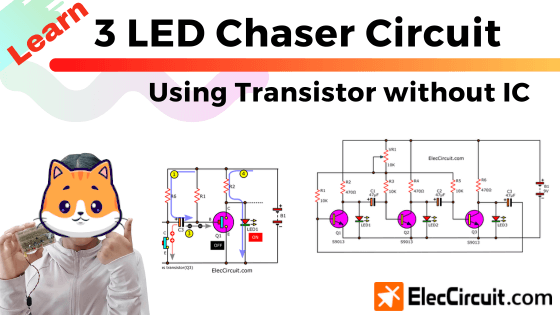
So she had a question: Can we use transistors instead of ICs? The answer is yes. Also, the LEDs can still flash in a chasing manner, like when using the IC.
We hope you guys will enjoy the transistor circuit as much as we do.
Circuit Experimentation
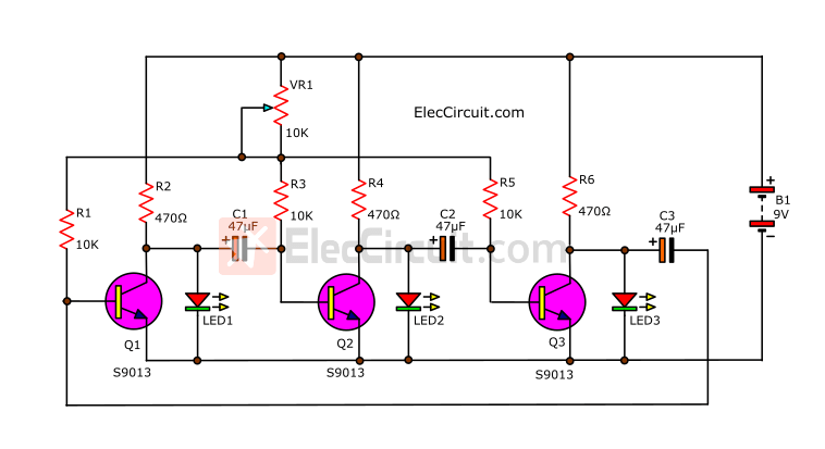
We will start by looking at the circuit shown in the picture below. This circuit is similar to a 3-LED flasher using a 3-transistor astable multivibrator. However, we changed the position of the LEDs, with different results.
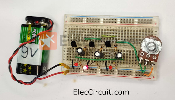
My daughter tried to assemble them on the breadboard.
Note: If you want an easier-to-see component layout on the breadboard, Let me know, and we will draw it for you.
Then, we adjust VR1 and observe the changes in LED1, LED2, and LED3.
When VR1 is fully rotated counterclockwise, all three LEDs will turn off. Because the resistance value is too high. But when rotating VR1 clockwise slowly, all three LEDs will start to turn on and off alternately. Until we see all three LEDs turn dimly because flashing is too fast for our eyes to see.
Understanding LED Chaser Circuit Using Transistor
Creating a circuit is not difficult. But understanding how it works is challenging for my daughter. But let’s try to learn them together.
Generally, we know that all three LEDs are controlled by transistors that turn off or on with the charge and discharge of each capacitor.
First, let’s look at a component whose operation we should understand: a transistor. In this case, it behaves like a normally open pushbutton switch.
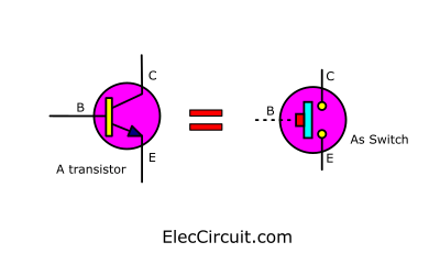
Its B pin is like a push button on a switch. But instead of pressing the button with our fingers, we use a small amount of current. So that a larger amount of current can flow from pin C to pin E.
Grouping
In the circuit, we will see many components connected together, which is difficult to make sense of. So let us start by dividing the circuit into sections or groups.
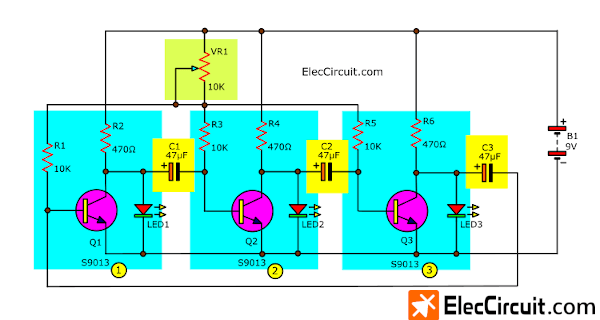
They can be divided into 3 identical groups.
Basic Transistor Circuit
Since all three were the same, we chose to learn the first one. which consists of Q1, LED1, R1, and R2.
We first remove VR1 and connect R1 directly to the positive of the power supply, as shown below.
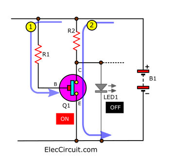
- A base current flows through R1 into the B pin of Q1 as a bias current. This causes Q1 to turn on.
- A much larger current flows through R2 and between the collector and emitter to the ground. Causing the VCE of Q1 to be zero or about 0.1V. So, the LED turns off because it requires a voltage of about 1.8V.
The LED will only light up when Q1 is turned off. But now it is getting a small positive bias current at the base.
Normally, if the base of the transistor gets reversed bias, It will stop working.
The component that can release the negative voltage is a capacitor.
So, we tested out a simple circuit, as shown in the circuit below.
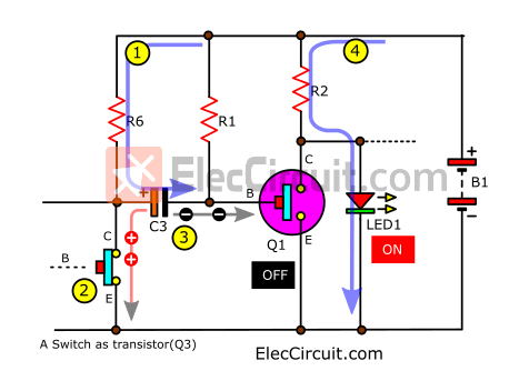
We add C3, R6, and a push-button switch as Q3 to it.
- The current flows through R6 to charge C3.
- Pressing the switch simulates the working of Q3, turning it on.
- Then, the current from C3 is discharged in the reversed bias at B of Q1. It receives a negative voltage, causing Q1 to stop working for a while.
- As a result, a large current flows through LED1, causing it to light up instantly.
But it only stays on until the C3 is fully discharged.
Understanding the full circuit
With the concept above in hand. Let’s now consider the full circuit.
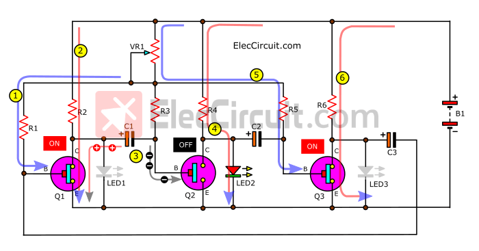
When LED1 is on
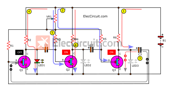
Let’s assume that the LED1 is the first and only LED to light up.
- When power is applied to the circuit, the current charges C3.
- Then, the Q3 will start up because of the bias current at its B pin.
- After Q3 turns on, C3 then discharges a negative voltage to B of Q1. turns Q1 off. And LED3 turns off because of its low voltage.
- The current flows through R2 to LED1. So, the LED1 glows brightly.
- The base current flows through VR1 and R3 to B of Q2. Causing Q2 to turn on.
- The collector current flows through R4, C, and E of Q2. This causes no current to flow through LED2, so it remains off because of its low voltage.
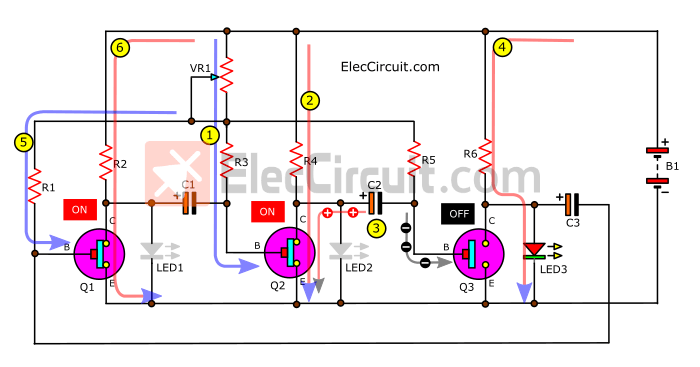
When LED2 is on
- When C3 is fully discharged. The current flows through R1 to B of Q1, causing Q1 to conduct between the C and E pins like a closed switch.
- The current can flow through R2, Q1, to GND. So there is no more current flowing through LED1, which immediately turns itself off.
- The C1 discharges a negative voltage to B of Q2. Causing it to stop working.
- Between pins C and E of Q2, it is like an OFF switch. Thus, the current flows through R4 to LED2 instead, lighting it up.
- The base current flows through VR1, R5, and B of Q3. Making Q3 work in the manner of a connected switch.
- The collector current flows through R6 to C and E of Q3 to the GND. LED3 turns off because there is no current flowing through it.
When LED3 is on
- When C1 is completely discharged, the base current can flow through VR1 and R3 into pin B of Q2, causing it to receive bias.
- Making Q2 work or turn on. The collector current can then flow through R4 through pins C to E of Q2.
- C2 then discharges its negative voltage, which stops the operation of Q3.
- The Q3 acts as an “off” switch. Now all currents that were flowing through R6 instead flow through LED3. Causing it to light up for the duration of the C2 discharge.
- The base current flows through R1 to B of Q1. Cause it to act like an “ON” switch.
- The collector current therefore flows through R2, C, and E of Q1. No current flows through LED1 so it turns off.
But when the discharging C2 current runs out. The base current can then flow through VR1 and R5 into pin B of Q3. Turning it on, and C3 discharges. Causing Q1 to stop working. Lighting the LED1 up again.
Conclusion
We can see that they always behave in this order. If the transistor stops working, the LED in that set will light up. Each duration is controlled by the value of each capacitor. For example, if we want to have LED1 stay on longer, then increase C3, C1 for LED2, and C2 for LED3, respectively.
From the result of experimentation with this circuit. We know that we can use a voltage supply ranging from 5V to 15V.
For capacitors in this circuit, we have tested from 10uF to 100uF; the higher the capacitance, the longer the LED will stay on.
If we want to add more LEDs, we will need to increase the number of transistor sets accordingly.
If compared to the IC circuit, this circuit doesn’t work as well. Sometimes the blinking is inconsistent. Anyhow, it is still good for learning about transistor circuits. Do not forget that all-powerful ICs consist of many transistor circuits that work perfectly together. Learning transistor circuits first is a good foundation for electronic work.
Get This
All full-size images and PDFs of this post are in this Ebook below. Please support me. 🙂

I love electronics. I have been learning about them through creating simple electronic circuits or small projects. And now I am also having my children do the same. Nevertheless, I hope you found the experiences we shared on this site useful and fulfilling.

Hi
Can you please supply me a simple circuit diagram for a 12v UPS for my router and fibre? I require this due to daily loadshedding in South Africa.
Thanking you in advance
Sew… Please email me
Hi,
Thank you very much for visiting our website. I sympathize with your problem.
I and my dad would like to try building this 12V UPS circuit for our house too.
Hope it will be helpful for you too. But we apologize in advance if it’s late for you. 🙂
circuit works great
Hi,
Thank you very much.
If you have any other suggestions for making the circuit more developed.
Please tell me and my dad. 🙂