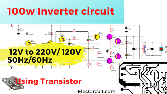
You can read books at night under a light. Energy from AC main makes it happen. But if you do not have an AC voltage. Do You still use a light? You need to use a 100w Inverter circuit and battery. Also, If you are outside a house, no electricity. You cannot use a lamp with a 12V battery.
This circuit is a mini inverter circuit using power transistor 2N3055 as the main component without IC.
It is designed for you that need to use appliances outdoor or no electricity. Someone use it in a car or the high mountain etc.
It can be converted 12VDC to 220VAC. The maximum output power about 100 watts. It is suitable for normal lighting (all home lamps), also used for radio, LCD TV, Stereo.
Someone uses it for a small soldering iron to repair or build many projects outdoor home.
How 100W inverter circuit works
See the circuit diagram below
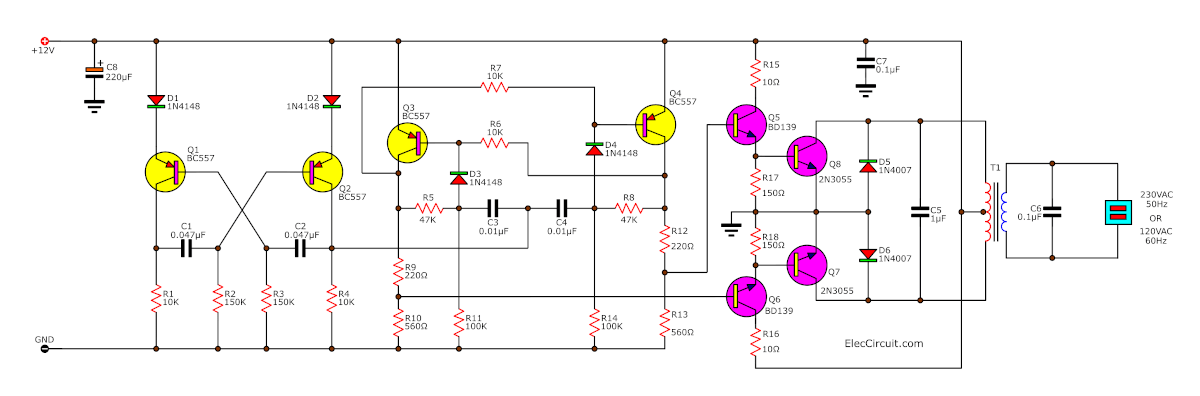
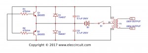
Figure 1, 100w Inverter circuit, 12V to 220VAC using transistors
This circuit will include five main sections as a block diagram.
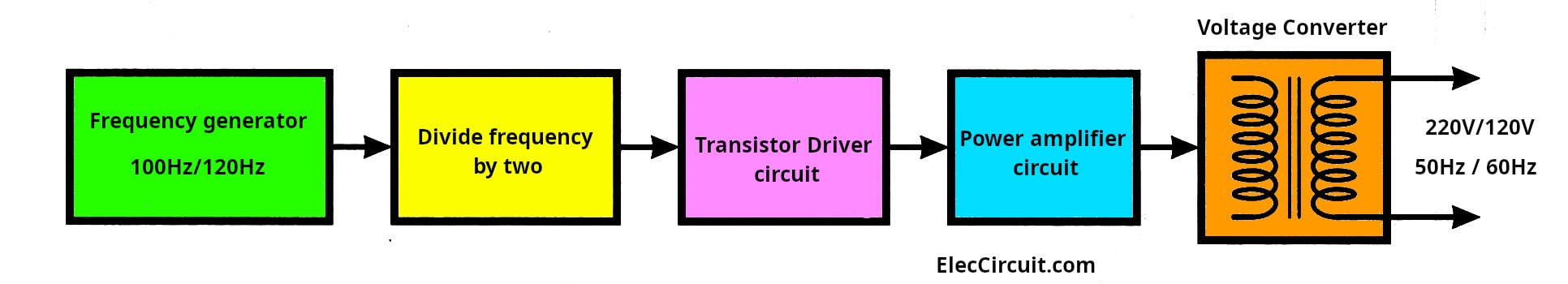
1. Q1 and Q2 act as the frequency oscillator circuit.
2. Q3 and Q4 act as the frequency divider circuit
3. Q5 and Q6 act as the transistor driver circuit.
4. Q7 and Q8 act as the output power amplifier circuit.
5. T1 is a voltage converter to power a load.
Here is a step-by-step process.
First, both PNP transistors Q1, Q2 will be connected together as the astable multivibrator form. They will generate the output frequency of about 100 Hz at the collector lead of Q2.
This frequency is set by both resistors R1, R2, and two capacitors C1, C2. And there are both diodes D1, D2 to set only positive voltage through the emitter lead of Q1, Q2.
Then, this signal flows through to the frequency divider by two. It makes the frequency is reduced down to about 50Hz.
Why designer does not set the circuit to directly work at 50 Hz. Because generating the steady low frequency is too hard.
This frequency has value the same as the AC main.
It will be a waveform of low-power alternating current. And, out to the collector leads of transistors Q3, Q4. Then, via resistors R8, R9, and R11, R12.
They are a voltage divider circuit to biased for driver transistors Q5 and Q6. To drive the power transistors Q7, Q8 alternately power the high current to the inductance coil in the transformer T1. It will induce electrical energy through the metal core from a set of 12V coils to an AC voltage of 220V at 50Hz to 60Hz for further use.
Note:
1. Normally, use the 2-3A transformers for 20 watts to 30watts for light bulbs. But you want 100 watts, you must use an 8A transformer. It is so expensive for me.
2. The primary coil of a transformer, you may use 9V CT 9V or 10V CT 10V or 12V CT 12V.
If you use a 9V CT 9V transformer. The output voltage will be 250V (approx).
Which normal I use 12V CT 12V, makes the output voltage about AC 220V (no-load). But with load, the voltage will reduce to AC 190V
3.This circuit will have output as a square waveform. So cannot use for inductor load.
But it’s enough for mini electrical appliances. Such as electric soldering iron, Digital TV, Mobile Charger, Small laptop, etc.
4. This transformer, we may use a secondary coil as the output voltage as you need. The example we connect to the power amplifier that uses AC 24 volts. So we use AC 24V secondary coil, etc.
How to builds
Similar to the various projects that have passed. To begin with, make the PCB or you can use the universal PCB(Perforated PCB). Then, assemble all parts on PCB as Fig. Next check all for errors. Check again and check again.
Then, apply the 12V 10A battery to this circuit. And use the voltmeter to measure AC voltage output. Next, connects the load to the circuit. is it easy?
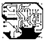
PCB layout
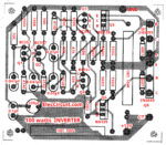
Components layout
PCB layout and components layouts of the 100w Inverter circuit, 12V to 220V using Transistors
Parts you will need
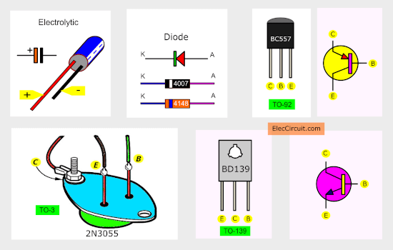
Q1-Q4: BC557, 45V 100mA PNP Transistor
Q5, Q6: BD139, 80V 1.5A NPN Transistor
Q7, Q8: 2N3055, 100V, 15A, 115W, >2,5MHz NPN transistor
D1, D2, D3, D4: 1N4148, 75V 150mA Diodes
D5, D6: 1N4007, 1000V 1A Diodes
0.5W Resistors tolerance: 5%
R1, R4, R6, R7: 10K
R2, R3: 150K
R5, R6: 47K
R9, R12: 220 ohms
R10, R13: 560 ohms
R11, R14: 100K
R17, R18: 150 ohms
R15, R16: 10 ohms, 10W Resistors tolerance: 5%
Ceramic capacitors
C1,C2: 0.047uF 50V
C3,C4: 0.01uF 50V
C5: 1uF 50V
C6: 0.1uF 250VAC
C7: 0.1uF 50V
C8: 220uF 25V, Electrolytic capacitors
T1: 220V/120V AC primary to 12V-0-12V,2-8A secondary transformer.
Be careful connecting components
Are components backward? You must connect them in proper pins only. Look at connecting correctly capacitors, Diodes, Diodes, transistors, etc.
For 2N3055 transistors, look at mounting it on the heatsink.
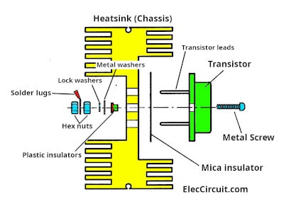
The screws should be tightened. Because a large amount of current flows through Pin C to Pin E.
Download This
All full-size images of this post are in this Ebook: Elec Circuit vol. 2 below. Please support me. 🙂
You may like these circuits, too.
GET UPDATE VIA EMAIL
I always try to make Electronics Learning Easy.
Related Posts

I love electronics. I have been learning about them through creating simple electronic circuits or small projects. And now I am also having my children do the same. Nevertheless, I hope you found the experiences we shared on this site useful and fulfilling.
This projets are so much helpfull
i want make a ups for only one electric fan please help me about this
i try to build this inverter but did not work. the one transistor 2n3055 is hot. please any body help me to work this circuit.
Is there any probs when we built this circuit in a breadboard……please help me
i have done everything but is not working. When i connect the power (battery 12v) is not giving any output at all.And am worry bcos that is my project and am working on it but still is not working so i want u to help me
It’s information very helpful me in my project”INVERTER USING SOLAR ENERGY” .
I want to make a 50 watts DC 12V to AC 120V inverter
So please help me.
I want to know about the cost of 6v, 8v and 12v w inverter circuit. pls help.
CAN U SHOW A SIMPLE TRANSISTOR ONLY CIRCUIT
FOR A 500 WATT INVERTER—-12VDC—-220V AC?
APPRECIATE-VERY MUCH FOR A CLEAR DIAGRAM THANKU
What type of transformer and of which rating should be used????
hi
I want to build a system that charging lithium batteries
its funny it works perfectly i tried it up todate its still working
its funny it works perfectly i tried it, up todate its still working
i needs a 500w inverter circuit any one can help me
i want to know the components i can use to build a 12v 7Ah 220v inverter 50w.please the ratings of resistors …not more than two transistor
pls l want the size of compunents that could be used to build an inverter that could power 100 wailt bulb.
which type of transformer you used is this a current transformer or simple center tapped transformer plz help me I want to build this circuit
thank you sir, it is agood idea.ihave worked it out for two years but still working.even i have improved it to 500W and beyond. God bless you.
i need help to build 5000 wait inverter circuilt.
hai sir i have mini inverter two lights and use TIP3055 and 2N3055 and more plese help me
Hi,wisdom
You can see: https://www.eleccircuit.com/12-volt-to-220-volt-inverter-500w/
but is 500watt only now I not have a lot of power watt inverter.
Hi,Arun
Thanks for your feedback.
Yes you can use TIP3055 transistor it is power transistor. I would like to use it. because easy to mount but it expensive than 2N3055.
Plz give how many ampr is required at input side in 12v dc battery?
12v dc but amp_?
and also tell me about the transformer rating, voltage_ and amp_?
Hi,Brijesh
Thanks for your feedback.
I used Car battery 12V 40Ah. and transformer 2A-3A.
I can use for laptop and 20w lamps.
simpley and nice projects i hink i is used home applyencants
Hi,subbu
Thanks for your feedback.
Hello
Site is very useful
I love some of the questions LaSalle
I would love to Create symbol such as this therefore sent this letter to you this Model
Micro Inverter using TIP41 or 2N6121 Eleccircuit_com.mht
I do not want to stochastic problems during the building and district corect me because I am beginner in electronics and components diffrant from one country to another and often for name
But I’ve found a wire size of 20 within the components and district did not understand his place in the circle
Is if it is used Transforma strongly 500 watts and district will bear you are working or collapse /
Secondly
Ask a circle called xenon raise electricity for the car battery front bulbs for cars and light color makes the car think the white circle enlarge Volt
I hope for your reply and help me
Thank you
Sorry for the poor quality of language translation and Google is also not good
hi
i Ask about Circuit called xenon raise electricity for the car battery front bulbs for cars and light color makes the car think the white circle enlarge Volt
[email protected]
thanks
hi
ineed inverter like this
web adress is arabtronics.net/products/INVERTER-KIT-W%7B47%7DT-12V-24V-220V-750W.html
[email protected]
Hi,Moha
Thanks for your feedback.
This circuit is easy: https://www.eleccircuit.com/micro-inverter-by-2n5121/
You can use TIP41 transistors or use this circuit:
https://www.eleccircuit.com/tag/mini-inverters/
This circuit 100watt inverter worked and you must use 8A-10A transformer for real watts output.
and 500watts output use must use 40A transformer.
You’re welcome. I also poor English If you not understand please tell me.
hi 4 all
momename thannks
Thanks so much for the founder of the site, which allowed us to posts and thanks also to his esteemed visitors
Ask the electronic circuit for xenon used in lighting the front of the car and gives a strong white light searched the forums English and found them talking about circles xenon flash any light intermittent and disco parties please help me with knives circles components electronic large-sized conventional and not system components printed and does not Electronics Small Size
Thank you
And you greetings
[email protected]
hi
momename
This line did not understand it the last line in the electronic components to build this circuit easy inverter
solid Wires no. 20 AWG length 1 feet, for what iam not understand is it for main connector or???please help me
thanks
[email protected]
mome.name
Hello
What is the reason that in the absence of even one letter omitted patient Xue
مرحبا
ما سبب الغياب ما في حتى رساله واحده بيها اصبر شويه ما الوعد بيناتنا الفه اغنيه سودانيه مهداه لحصرتك
mome.name
mome.name
Hello
What is the reason that in the absence of even one letter omitted patient Xue
مرحبا
المهندس الغالي
ان كنت تتكلم العربيع يجب ان نتخاطب بالعربيه في رسائلنا القادمات واشكر رحابة وسعة صدرك وكرمك الفياض
ما سبب الغياب ما في حتى رساله واحده بيها اصبر شويه ما الوعد بيناتنا الفه اغنيه سودانيه مهداه لحصرتك
mome.name
hi
4all
who is inverter can run fans and motors sny inverter or none
thanks
Hi,Moha
This circuit cannot be used for AC fans or AC motor because it is square wave inverter.
I am sorry now not have sine wave inverter.
Thanks for visit.
hello its prits again.. i want to know about the cost of total circuit..
Can you please give me the list of all components……….and how many amps of transformer and battery you are using…..plz
sir!
i want to apply this idea in my final year project please send me more detail about Inverter 12V to 220V 100W by Transistor.
i want to submit proposal on this topic for my final year project
[email protected]
Hi, prits
Thanks for your feedback.
Please look at text above again.
Hi, Sam
Thanks for your feedback.
Now I add the parts list, please look at text above again.
Hi, tahir
Thanks for your feedback.
Please read again.
Hey needed circuit diagram on how to make mppt solar controller regards
Hi, simon
Thanks for your feedback.
Now I not have the high power controller.
But sometimes you may idea from simple circuit look at https://www.eleccircuit.com/battery-chargers/
total spend on this above cited project
thanks for give us this information.
Is that Inverter 12V to 220V 100W by Transistor will work properly………….?
12ct12/230v what is 12ct12
Hi amol,
Thanks for your feedback.
Please look at T1___230V AC primary to 12V-0-12V,2-8A secondary transformer.
CT = center trap
Very good.
I want to apply this idea in my final year project please send me more detail like abstract and applications about Inverter 12V to 220V 100W by Transistor.
Can 2n3773 work
100 watt
Can I use 12v 7A battery for this project?
I Tried this circuit.But its not working.The 10ohm resistors are burning when supply is given.
help plzz
when i done this circuit on breadboard both the 10ohm resistors got burned. please help me…
Hi, Saud
Yes you can.
Hi arun,
Thanks for feedbacks.
Please check circuit for error again.
and Check polarity of both diode at power transistors.
I don’t have transistor BC139 and resistor 10ohm 10 watt what other transistor and resistor can I use instead of that transistor and resistor ?
Is it BC139 Transistor or BD139?
Because in the figure it is BD139 but you wrote in part list Q5,Q6 BC139
Hi, Saud
Thanks for your feedback.
I’m sorry for error in list Q5,Q6 = BD139
What other value of resistor 10ohm 10 watt can I used because i didn’t find 10ohm 10 watt?
sir im getting 12v at input side of transformer before conectng transformer… bt wen i connect transformer voltage become 6v and im getting nly 110v output from transformer. please help me. im using 12-0-12 to 230v ,3amp transformer.
The mistake was mine.There were error in connections.But another problem now is i cant simulate it in protus with some load connected to it.
can someone help please
use full
I just wanna design a 1000watts pure sine wave inverter can u assist me knw the suitable ratings of the transform I am to use in my design otherwise assist me
SIR MUJE AP YA POCHNA HEY K
12v 7Ah /
12v 2AH
converte kar sa te hey
All about was good but I need a 100 watt output inverter to use as input power for operate a 1000watt inverter with full load. Give me a giagram for the same.
plz help me for making my miner project I don’t decided which project we make
Hi friends
I have one doubt about inverter. Many of circuits are available via net but lot of circuits output power is not given. So my question is how to calculate output power of inverter.
I am trying connect the circuit in PCB what am supposed to use for the transformer and center tap and how can I connect it will be help full if you guide me as soon as possible . If you build this circuit in pspice that will be great .
-thank you.
This is not giving any output
What device can be at source 12 volt and 10 A
One 10 ohm resistor is getting hot but another one is not. Frequency divider circuit’s 2 output’s are different voltages. I checked my connection and element’s values. There is no error. Then I don’t understand what’s wrong. Reply please
by changing battery (i.e…10amps-45 amps).can wattage be increased
when i connect 12 volts to circuit . battery voltage decreasing to 6v and output is 6v-0-6v.plz help me.remaining things are perfect
Sir , where we can get the specified boards to suitable to your circuits of battery charger, home inverters?
sir…its so need to know me….is this possible 6volt dc to 12 volt dc..inverter?. please if you tell me and give me the diagram….I want make it…
i want to repair the power supply that convert from 220vac to 24vdc.it is cut off .
When ibobserve the picture i do not undetstand that a line in somewhere is it touch or not touch
Hai, can u please give me a solution for my question it is that how to produce 7amps current as an output by giving dc voltage as an input to the circuit , one important thing is that without using transformer please help me guys.
How to design 36v charger control