Sometimes, we need to measure a too tiny AC voltage level. And high frequency too. Ohh… We cannot use general multimeter.
I recommend you try watching the AC millivoltmeter circuit. It includes the 6 ranges. Lowest is 15mV only.
Also, it uses an analog meter form. So, you can watch easily a slow changing of voltage.
Of course, It can check a high-frequency signal of 100 Hz to 500 kHz. So, suitable for audio your projects.
How it works

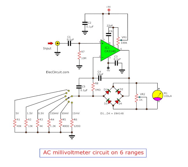
See in the circuit diagram above. This circuit can easily measure the very tiny AC voltage and high frequency of 100 Hz to 500 kHz.
Use an op-amp is the input is MOSFET types, so has input impedance about 10 M ohms. The lowest full scale of this meter is 15 mV on a galvanometer 100uA.
A galvanometer is a very sensitive meter to measure tiny currents, usually 1mA or less.
It is analog multimeter, cheap and somewhat accurate.
Best for observing the trend of a slowly changing current.
This op-amp has 2 functions are an amplifier and an active rectifier. The gain can be selected by six the resistors (R1 to R6) to switch SW1, and this resistance can set full scale, be divided by 100uA.
For example, If we need 200 mV range we will use the resistor is 2 K ohms.
This circuit have 6 ranges are: 15mV, 50mV, 150mV, 0.5V, 1.5V, 5V
The bridge diodes D1-D4 are the feedback of the amplifier circuit. Thus, must have the offset circuit of the diodes’ threshold voltage, to scale of the meter is a linear.
Adjustment zero on meter
Short input, adjust P1 to read really zero. Then feed the reference to input, adjust P2 to correct reading. The accuracy of this circuit based on the value of R1 to R6.
The circuit uses current very low. So should use two 9-volt batteries to long times life.
The parts you need
IC1: CA3140
D1-D4: 1N4148, 75V 150mA Diodes
C1,C2,C3,C5: 100nF or 0.1uF 50V ceramic.
C6: 22pF 50V Ceramic
C4: 10pF 50V Ceramic
0.25W 1% Resistors
R1: 40K
R2: 12K
R3: 4K
R4: 1.2K
R5: 400Ω
R6: 120Ω
R7: 10M
R8: 1M
P1: 100K Pot (Preset)
P2: 1K Pot (Preset)
M1: 100uA galvanometer
GET UPDATE VIA EMAIL
I always try to make Electronics Learning Easy.
Related Posts
I love electronic circuit. I will collect a lot circuit electronic for teach my son and are useful for everyone.


Mr how can i see the output ???
the diagram is not good . two errors
d1, d2, d3,d4 are not in the good position
the resistance for 200 mv is not 2kohm but 1600 ohm !
Hello, garbe,
Thank you for your advice. It is correct.