Here is a simple Solid State Relay circuit. Why should it? Imagine you need to control a load with AC Main. Often you use power relay to turn on-off the load. But in some cases, you cannot use the relay. Such as, In areas that are sensitive to sparks. There may be a spark while the relay is working.
How it works
Imagine A solid-state relay circuit that in common use design to be controlled by the input voltage from 3V to 24V.
However, in actual usage. We found that at low input voltage. Performance of the circuit is decreased. Because the most input circuits will be using the resistor to control the current flows through the LED transmitter.
On as, low-voltage doing the current is very small so that the output circuits to drive the Triac gate current reduced, the current flowing through the load decreases. If the lamp is a load, it is obvious that the lamp does not light or reduced light.
Modifications may be made by reducing the resistors. When used high input voltage. The current that flows through the LED transmitter will too much until it may be made damaged.
To resolve this issue. We designed new inputs circuits, so supply to the LED transmitter is the current constant at all level voltage input.
Recommended: How does an SCR work
The operation of the circuits
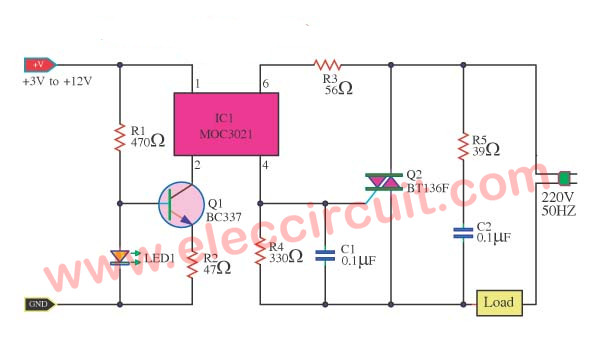
From the circuits can be seen that the transistor Q1 acts as a constant current to the LED transmitter within IC1- OPTO ISOLATOR.
When we attach the R1 to the LED, the base voltage of Q1 will be a constant about 2 volts and at emitter pin of Q1 also as about 1.5 volts.
From the value of resistor R2 in this circuit, we will have a constant current flowing through the transistor Q1 and the LED about 30 mA to the output also constant current at pin 4 of IC1 to drive the gate of the TRIAC.
So, the current flowing through the load is a definite quantity, required at all times.
How to builds
To begin with, you have to make PCB layout board, Secondly, you have to put all components as layout on Figure 3 by we solder low parts before and follows with a higher components. The triac Q2 should Be attached with an appropriate heatsink.
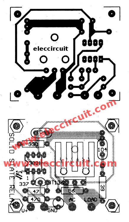
Figure 2 The PCB and components layout of this The professional solid state relay projects
GET UPDATE VIA EMAIL
I always try to make Electronics Learning Easy.
Related Posts


I love electronics. I have been learning about them through creating simple electronic circuits or small projects. And now I am also having my children do the same. Nevertheless, I hope you found the experiences we shared on this site useful and fulfilling.
This seems to be a viable solution, I still have to try it. But what if the controlled load is D.C. instead of A.C. load??
any solution for D.C.Load control. If S.C.R. is used in place of triac, What changes needs to be made?
I like this circuit, it is very importance to me, I’ll try
Its very useful circuit. Need some details about the components like the wattage values of resistor and voltage of the capacitors.
Can you pls advise what is power rating for resistor and vol rating for capacitors. Thanks
Hi, Can you pls advise what is the size of PCB w.r.t actual size.Do reply.
It looks like the circuit that I have. But when I do a simulation I get a power loading of R3 of 36 watt. How do I get a resistor that can take that? My load is a water pump 220V, 350 watt. I have measured the resistance through the pump to 26 Ohms, but I dont know the induction of the pump (Henry). I have fried an optocoupler (in fact several).
Can you help?
It is interesting that solid-state relays have a 3V to 24V input. I don’t know much about relays but my wife has been practicing her soldering and asked for a few DIY projects that she can do. I may consider giving a few solid-state PCB relays to her for Christmas.
Hi
You are great. You are lucky.
Electronic activities are not boring.
Have fun in this new year.