Do you feel tired muscle? You may try this, a simple portable electronic pulse massager circuit. It will help you relax the muscles with a frequency pulse.
Ideal for those muscles all the time, such as standing or hand throughout the day. This machine is small And is powered by 9 volts battery, so it’s safe. You can also customize the frequency and strength as well.
The working principle
Look at Figure 1 is the Simple Electronic Pulse Massager circuit diagram. It uses 9 volts battery.
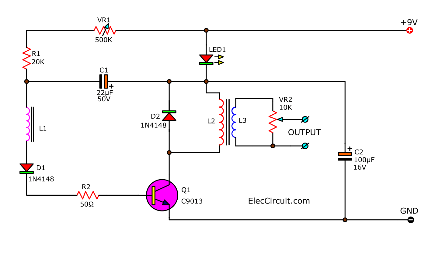
Figure 1 is a Simple Handheld Electronic Pulse Massager circuit using CS9013 transistor
The working of the circuit will begin with transistor-Q1 is connected as the frequency generator circuit.
Which this frequency will depend on R1, R2, C1, C2, L1, L2 and VR1. We can adjust frequency by VR1.
Read first for beginners: How do transistor circuits work
Then, LED1 will flash as a frequency that it generates. Next, it is increased to step up an input voltage from L2 to L3.
It has a high voltage pulse of about 50 volts, output. And it is pulse narrow range and lowest current, too.
So, Not harmful to the user in any way. This voltage will flow to VR2 to adjust the pulse voltage before sending it to the output.
Recommended: ECG simulator circuit using CD4521 and CD4017
How to assemble circuits
First, we make the PCB as Figure 2 that is an actual-size of Single-sided Copper PCB layout.
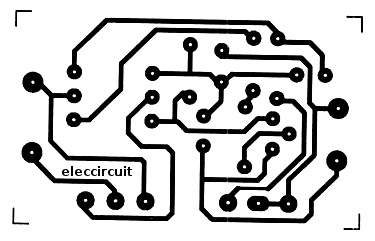
Figure 2 actual-size of Single-sided Copper PCB layout.
Then, assemble components as Figure 3 is the components of PCB. By putting all parts that lower than higher such as Diode, resistors, etc.
Learn more: about Electronic circuits
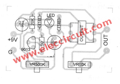
Figure 3 The components layout and wiring.
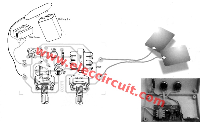
Look at Figure 4: The really using application of this project.
Read other: Electronic Pulse Massager
The testing
When we assemble the circuit successfully as Figure 4.
- Then, apply a 9 volts power supply from battery by a positive polarity to +9V and the negative polarity to GND of this circuit.
- Now, LED1 will flash.
- Then test to adjust the VR1.
- Next, notice the flashing of LED1 will slowly or fast as adjusting VR1.
- If you try as above, it shows that this project ready to uses.
Read Next: How to make 1.5V to 220V inverter circuit
Application
We should connect both output point with a metal plate, then place them on the body, the two points a little apart.
Next Cover with a wet cloth next to the modest size of 5×5 inches.
After that adjust VR2 to the full left. Then, apply voltage to the circuit. Next, rotate partially the volume to the right.
Our muscles, it will begin to pinging and more. According to the strength of adjusting VR2.
Then, try to rotate VR1 to change frequencies as needed.
Repair of this project
1. LED lights throughout, showing that C1, C2 short. And pin CE of Q1 short.
2. LED flash but tried, muscles do not jerky, indicating that the lack of L3.
3. Adjust the frequency did not, indicating that VR1 shock.
Component list
Resistors size ¼ W +-5%
R1: 20K
R2: 50 ohms
Potentiometer
VR1: knob 500K
VR2: with knob 10K
Capacitors
C1: 2.2uF 50V Bipolar
C2: 100uF 16V Electrolytic
Semiconductor
LED1: 5 mm LED 5 as you want.
D1, D2: 1N4148 0.75A 200V Diode
Q1: CS9013
Others
L1-L3: the small output transformer, TO-601
Universal Box
SPDT- Single-pole double-throw switch = 1 Pcs.
PCB as Figure 2, wires, etc.
9V power supply circuit
Note:
Flatron said” L1,L2 and L3 is output transformer.
This transformer is an old components.
(I thing is is 2×600 ohm/8 ohm transformer)
it’s primer side 3 pin (2 bobin)and seconder side is 2 pin(one bobbin)
“
Thanks!
Instructions for use
1. Do not use both metal plates touching the head or temples.
2. Do not use on pregnant women
3. Do not apply a DC adapter instead of 9 volts battery.
4. Cases, the side effects, should see a doctor immediately.
5. Do not bring both metal plates to the area of the wound.
Check out these related articles, too:
- Small High Volts shock using 2SC1815 transistor
- DC Voltage Doubler and Voltage Multiplier Circuits working
- 5V to 12V boost converter circuit or higher using transistor
GET UPDATE VIA EMAIL
I always try to make Electronics Learning Easy.

I love electronics. I have been learning about them through creating simple electronic circuits or small projects. And now I am also having my children do the same. Nevertheless, I hope you found the experiences we shared on this site useful and fulfilling.

I CAN NOT UNDERSTAND THE OUTPUT TRANSFORMER DETAILS. IS IT FERRITE CORE ?
PLEASE SEND DETILS.
THANKS.
How do i make L1, L2 & L3 transformers?
Por favor,necesito detalles de L1,L2,yL3.
Muchas gracias
Onurba
need details for L1,L2,L3 can you send
thanks David
[email protected]
L1,L2 and L3 is output transformer.
This transformer is an old components.
(I thing is is 2×600 ohm/8 ohm transformer)
it’s primer side 3 pin (2 bobin)and seconder side is 2 pin(one bobbin)
*if you folow circuit on pcb image you will understand
Thanks your help.
There are three holes on both sides of the PCB where the transformer is located.
While the transformer has two outputs on one side and three outputs on the other side.
Please explain in more detail.
The transformer has two outputs on one side and 3 outputs on the other side. While the location of the transformer on the board has 3 holes on both sides for the output of the transformer.
Please explain more about this.
thanks
what is the frequency and amplitude of output pulse generated by this massager?
I could not get exactly how you made transformer using inductors L1, L2 and L3. I’ve traced their positions using the pcb layout you provided but don’t know of what values they are?
how to make or winding out put trans for mer.what is conection circuit and pcb layout not match
using ENGLISH words is not all there is to speaking ENGLISH. the ENGLISH language also requires ENGLISH sentence structure, which most of your word structure lacks, making your message hard to understand.
Hi Steve hoke,
Thanks for your feedback.
we don’t know about transformer u mentioned
we want details about it
I CAN NOT UNDERSTAND THE OUTPUT TRANSFORMER DETAILS. IS IT FERRITE CORE ?
PLEASE SEND DETILS.
THANKS.
The output of the circuit should be connected to a piezoelectric element to convert the electrical oscillations to vibrations(massage), so please tell me what are the specifications of this piezoelectric plate like:
– Frequency depending on the frequency range of the massager circuit.
– Voltage and current.
– Power consumption.
– Compatibility with the human body and durability.
And could you please tell me also, what is the types of the coils used?