24 LED Decorative light circuit using NOT Gate
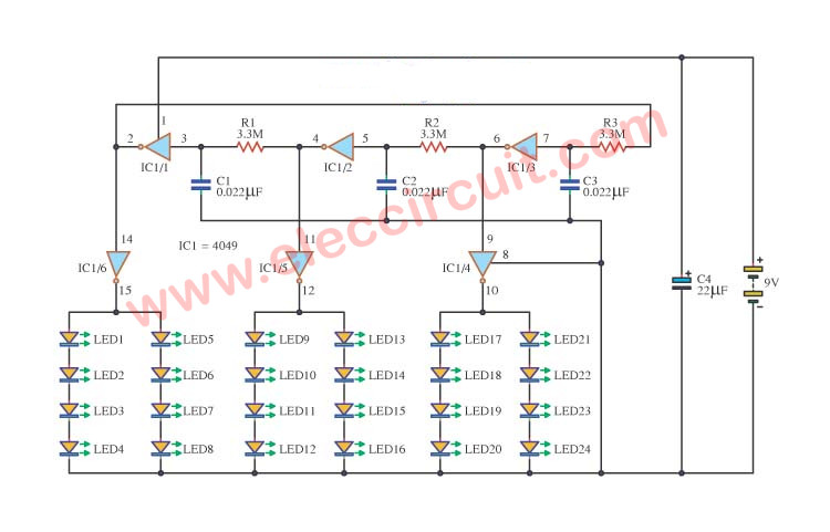
I am going to show you, LED Decorative light circuit. Do you like a LED blink or running light? I like a circuit like this. Although you will do not build it now. But it also a good teacher, right? If you have ever been to use a LED flasher. Some may wonder how the … Read more