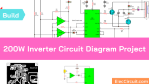
This is inverter circuit 500W output. It will convert 12VDC to 220V 50Hz. You can build it easily and inexpensively. Friends favorite this. Because like working outdoors, or to backup storage to use when necessary. Most of this is circuit low power, which is not suitable for practical applications.
My friends said that he would be about 500 Watts. It is a good size. Use with television receivers and light bulbs as well.
How it works

When looking for the circuit. I get headaches. If you are a beginner or I cannot buy expensive good quality circuits. Requires only one transistor. Or if you have free time. I want to build an old circuit is alive again. This circuit will accommodate all your needs.
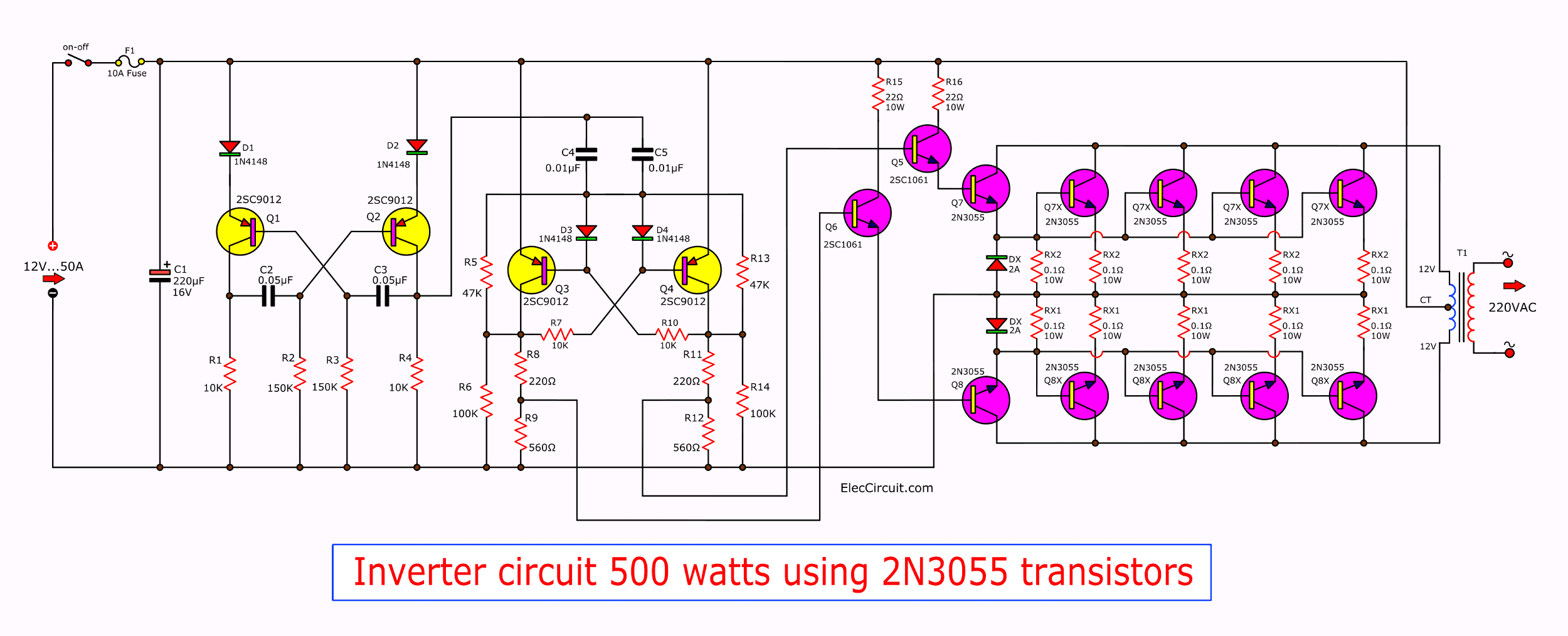
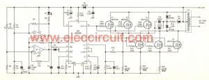
It is a simple circuit. The same principle, I take battery voltage 12V to produce an oscillator about 100 Hz and pass to a two frequency divider circuit is only 50HZ. And drive a 10-ampere transformer with 10 x 2N3055 transistor in parallel. By a single transistor has 2A, when I use 10 transistors or 5 pairs of drive high current output.
The complexity of circuit, but the principle is not it, and it is the number of transistors on a basic, easy to buy. You may be modified 100-watt power inverter To the size of transistors and transformers as well.
Note:
1. Battery for these projects.
If you need 500 watts output. Your battery must be 45Ah. (500w/12V = 41A).
Maximum current for 1 hour.
2. The solar battery charger( 18 volts solar voltage)
Full sunrise power on a day about 5 hours.
So you need current from the solar is (45A/5hour = 9A)
or 9A x 18V = 160 watts.
Learn other Inverter circuits

Is it difficult for you? Let’s see an easy circuit better.
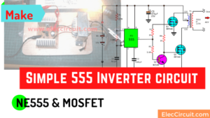
Make 555 Inverter circuit
Do you want to learn a simple inverter circuit? The output is about 50 watts. And using a few parts and a small circuit.
Here is an IC 555 inverter circuit. Because of using 555 timer and MOSFET as main. I experiment it to work well.
DC to AC Converter circuit
Using CD4047 and MOSFET, transistors output max 60 watts
This way is easy to make, small.
The 12 volts of a Car battery and converted to AC 220V 60 watts. Then apply to appliances easily. And portability easy with Because of the small. In-circuit we use CD4047 and BD249 as the main part so is a mini circuit.
How to make simple inverter circuit diagram within 5 minutes

In the two Circuit diagram below, just use 2 transistor, 2 resistors, and one transformer only. They can convert 12VDC from battery to 220VAC or 120VAC to apply small light bulbs or lamps max 10 watts.
Also 500W inverter circuit for you
If you think that This circuit is not good enough. For your work. It is hard to find equipment. You do not have it now. These circuits may be viewed below. It may be appropriate for you.
1. Inverter 500W 12V to 220V By IC 4047+2N3055
Using this circuit you can convert the 12V dc in to the 220V Ac. In this
circuit 4047 is use to generate the square wave of 50hz and amplify the
current and then amplify the voltage by using the step transformer.
How to calculate transformer rating
The basic formula is P=VI and between input output of the
transformer we have
Power input = Power output
For example if we want a 220W output at 220V then we need 1A at the output.
Then at the input we must have at least 18.3V at 12V because: 12V*18.3 =
220v*1
So you have to wind the step up transformer 12v to 220v but input winding
must be capable to bear 20A.
2. 500 watts MOSFET power inverter circuit
As 200 watts inverter circuit. We use Q1, Q2 is the mosfet acts as a power output. That can withstand currents up to 18A. According to properties listed in the table of Figure 2. If the circuit is fully functional with maximum power of 12V x 18A = 216 watts. But in practice, the circuit should work up, it may be damaged. Therefore, it is designed to operate up to 200 watts.
Since we want the current more than 40A. But the power mosfet single, able to withstand current is 18A, therefore have to be 3 pcs. And When designing a circuit in a push-pull model thus requires a power mosfet 3 pairs.
We have the output current up to 54A which can withstand more demanding than 14A. It is good for the operation of the circuit. Because each power mosfet will not be overburdened. And the heat of the mosfet least, the lifetime of the life circuit.
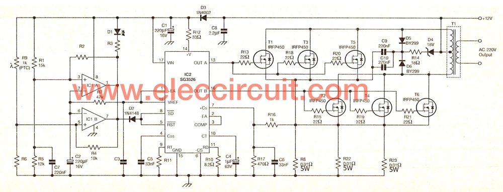
Then see circuit diagram below:
The schematic diagram of this projects
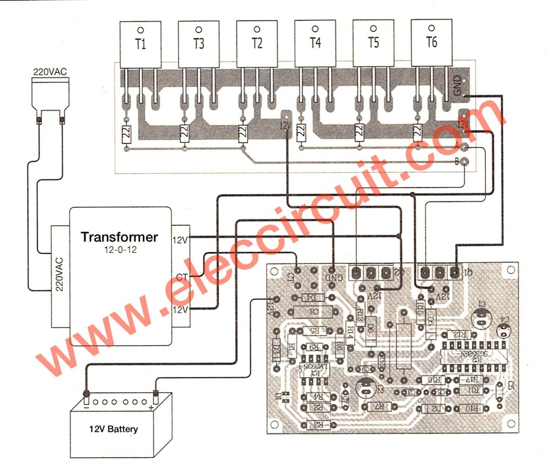
This is full components layout
You can look more : 500 watts MOSFET power inverter circuit
Related Posts
I love electronic circuit. I will collect a lot circuit electronic for teach my son and are useful for everyone.
This projects they are helping our school
I’m Brasilian, this project it’s very simple, but efficient!
Thanks for your feedback.
Please sir, is it possible to inprove on this circuit to produce 1.5kva? If possible, how can i go about it?
can i have a enlarged and clear image of circuit
just contact me if you want asimple lw cost inverter 12v to 110 1nd up ac
Gostei muito deste projeto vou tentar montar assim q tiver um tempinho…
This project is simply great. If this could be upgraded to 1.5kva pls tell me how to go about it.
Hi guys please could you send me a clearer and enlarged circiut and if the circuit can be uprated to 1.5kw please advise. Thank you
hey guyz.. what is DX and RX in schematic ??
please what is the meaning of DX 2A, and what diode can we use as equivalent of 2A. Thnx
In this curcuit, if connected it with 12v/5a battery, what is the output voltage and current?
can i use only 4 2n3055 transistor??
when i do simulation on proteus.. i did not get the output 220
Hi, Michael John
I suggest not should build your own. Because it has low performance. And more expensive.
You can buy 1500 watt shop or https://www.amazon.com/gp/product/B00126IDDC/ref=as_li_ss_tl?ie=UTF8&tag=all_electronic_components-20&linkCode=as2&camp=1789&creative=390957&creativeASIN=B00126IDDC
Hi, @seen
You can use 4x2n3055 but lower watt than this circuit about 100-200 watts.
and
The transformer not need layout on PCB because it big size.
Hm..i already made this circuit inverter and i read some questions that need help. The resistor w/out wattage is all 1/4 watt cfr,and the 1N414B you may use 1N4148 for fast switching,and also the DIODE DX2A it means its a diode,you may use 1N5402,and to be able to have an output fix to 500 watt the transistor should be 14 pc’s and it means 7 channel bec.the 1st stage of 2n3055 is just to switch on or power the other channel..RX Is also mean it is a resistor 10watts 0.01ohms wire wound and also remember the 22ohms 10 watt is also a wire wound and should be in heatsink or blower coz it will be over heated in hour of used just in case..thanks for this circuit i never worry in black out here in our area philippines..thanks autor and admin..
My mistake the RX should be 10 watt 0.1ohms i just corrected it..peace
admin,
thanks 😀
@seen You welcome I am not good electronics.
I like collect electronic circuits only.
can you give a lil explaination of 100ohm 1/4watt? can i use 100ohw 5watt instead?
Junrev, have u finished with your simulation? is the output produces 220VAC?
@lah yes i already finished it and it works great,yes the output is 220V 50hz but if the battery is fully charge it will be about 225V believe me the circuit works great but you should put a heatsink or blower in resistor 10watt 22ohms to prevent over heating and use 14 pieces 2N3055 instead of 10, the costlier one is the best,for ex. The toshiba 2n3055 is the best i can suggest..and also be carefull when building it,.c0z it will harm you,make sure the connection of the transistor is correct coz once you have an error specially in 2n3055 transistor all of them will be leak or shorted so do it with care..sorry for my bad english im not really good on it..peace
@try and field the 100ohm 1/4 watt in the 1st channel between DX2A is ok but if you like to make it 5 watt sure why not?.much better but never change the value of the 100 ohm..
@junrev you using transformer cnter tap 500VA??
@junrev do you have a simulation or picture for that inverter..
I have made that inverter for my final project using circuit above…but it not working..
hmmm. 🙁
can you give me something for me to troubleshoot..
@seen yes i used 500VA center tapped transformer tamagawa brand.maybe you have an error…sorry i dont have a picture of it..do you really know how to read schematic diagram?. If you have a mistake the circuit wont work specially transistor..know how to read the base,collector and emitter..i suggest to check the all transistor coz maybe you already damage it..try to check the connection or wirings..and check also the diode polarity..thats all i can help…if you really dont know how to read schematic i suggest you to practice it by the help of professional technician..im a technician but still im moderate in electronics..peace…
sir ,if the .1ohms 10w,it is ok or not…what is the purpose of that resistor?
sir ,what is the purpose of the resistor .1/100w?
sir ,what is the purpose of the resistor .1/10w?
sir, what will i do if i want to have an output frequency of 60hz?
if I may ask are the 2n3055 transistors Bases connected together?
And what if I use TIP3055 transistor instead of 2N3055?
also can I use 1ohm @ the emitters of the 2n3055 transistors?
What does the RX2 mean
sir your circuit is 50hz how to become 60hz what component shoud be change
i need help of u. can u tell me how make 1500watt inverter by using 12volt through power plant or dainmmo system.
Hm..many questions but still no answer.. If you need an inverter and a pro electronics engneer search the circuit of swagatam majundar he is kind and willing to help you all. He is good in electronic and all of his circuit will surely work.. Peace
i need a 2kva transistor circuit diagram pls.
my email, +2348121690801, +2347030418159
kindly send me the diagram for 2kva transistor inverter circuit. to my email. [email protected]
Pls, fellow Engineer. I need cct diagram and full explanation of 1.5KVA Inverter. pls my email : [email protected]. thanks.
Provide me inverter circuit
How can i made 1000wats inverter?
I think,if anybody want a higher wattage of the inverter,then u hav to alter the wattage of small value resistor like the .1ohm to higher wattage,and add another stages of the power transistor(e.I)3055 and replace the transformer volt amp rating with a higher vamp rating.u can also utilize your inverter into making it a charger so u won’t need another gadget to recharge your battery.,just by adding a couple of heatsinked diode or rectifier,a capacitor and a dpdt switch ..to those who want to make the 50hz frequency to become 60 it is not impossible but a very complex ckt you will have,a costly one.anyway u still get a square wave on the scope which is not suitable for some device or appliances.
ahmp does the 50A current rating of the dc voltage source affects the output? how?
The work is Good but hw about the transformer, hw is the recoiling gona be
ahm… this is great 4 me….. while im in d first yr. of E.C.E…Thanks sa diagram…
الدارات جيدة ولكن نحتاج الى دارات ذات استطاعة أكبر وتعمل بشكل الي عندما ينقطع التيار 220 فولت وعندما يوصل التيار 220 فولت تشحن البطارية
can i use 2.2 ohm/5w resistance instead of 0.01ohm /10 w
what kind of this transformer? is this available or common in the market? how much the amper of this transformer? reply pls
what kind of transformer
it is the transformer that has primary winding of 220V ac and the secondary have center tap output of 12v? how much the amper? reply pls. because I choose this for my thesis… in this month
i mean the output secondary of the transformer have 12v 0 12v?
hello fellas i correctly followed the schematic diagram then finished it, and the inverter produces output of 220vAC and worked for just only 20 seconds with a Load (bulb) ( the 22ohm 10watt seems hot ). after that 20 secs, the output voltage decreases slowly to 190, 180, then jump to 54vAC. so bad not reading this posts
so i’m gonna follow what @junrev recommend.
i’ll post again..
-Philippines
I want the PCB for this project.
Thank you
Hello, i want an qualified personel to wind the output transformer for me. but i want to know what size(guage) of wire and how many turns of both primary and secondary will be appropriate to achieve the 500w?
Pls I am expecting reply. help me. Thank you,
how many watt use R1-R14, need transformer specification and how much time backup from this
Inverter ?
thanks,
Shahin Reza
Can you send me an proposal for the PCB – I ask this some time ago
Please sir, i made this inverter sir and i realy love it but pls can i be using it with a solar panel of 5w 12v without using battery for it backup? I want to be using it for charging phones and lamp at day time (8am to 6pm). Please sir i will be very happy to hear from u sir! Thank you sir
Am yusuf ;Please sir, i made this inverter sir and i realy love it but pls can i be using it with a solar panel of 5w 12v without using battery for it backup? I want to be using it for charging phones and lamp at day time (8am to 6pm). Please sir i will be very happy to hear from u sir! Thank you sir;;;;;;;;;;;
Please sir, i made an inverter of 100w sir and i realy love it but pls can i be using it with a solar panel of 5w 12v without using battery for it backup? I want to be using it for charging phones and lamp at day time (8am to 6pm). Please sir i will be very happy to hear from u sir! Thank you sir
Thank you
Hello sir, I’m Ganesh studying Bsc Electronics final year. this is my project sir. please help me sir how to build this 500 watt inverter circuit. I have made that inverter for my final project. but it not working..
hmmm.
can you give me something for me to troubleshoot..please sir pls
Hello sir, What is DX 2A ? Is it 1N5402 ? and What is the value of RX1 and RX2 ?
Is there any problems when we built this circuit in a breadboard……please answer me….Peace
I want to know about the cost of this 500 watt inverter circuit
Reply me soon pls….
Please, I like to know the difference between this listed components: DX and D, RX and R, QX and Q. Please kindly assist on this listed components
i made one of it, its really effective… use it with 12-0-12 transformer (12 amperes)… this is one of my project… its compatible with 200 watts solar panel…
Sir, I’m want to build this circuit but, can you send me the aspects of the parts (in full details) because this will be my first time to make a circuit,. I’m just curious about how inverter works. so I planned to search it and I found this site. Please send me the full details of the parts so that I will just make a list of it when I buy in electronic store. also sir, if you are able to give me the instruction, give me as well… Sir, and I hav Solar panel in my home, max. 20 v, and 300mA… I’m planning if possible i could charge my phone, using this circuit and the panel… (I need ur opinion about this) Thank you very much sir!!! 🙂 Send me, thru, yahoomail. @ [email protected]
hi, friends,
I made a small Inverter. It is working fine, kaaka pothe daanni Guddalo pettukunnanu. Shock baagaa kottindi. Guddantha manta kethu kondi.Naa gudda chinnagaa ipoyye Maadipoyindi.
MORAL : Dont make inverters.
didiculus circuit …
ridiculus inverter with out output controlle veri not good
inverter with 500 watt need a feed back controlle
try to create inverter but my did work that all
i use transtor 2n3055 and resistor but i use 12v adapter to power it
wot if i try with two transistor will it work propery
Hello, i want an qualified personel to wind
the output transformer for me. but i want to
know what size(guage) of wire and how
many turns of both primary and secondary
will be appropriate to achieve the 500w?
Pls I am expecting reply. help me. Thank
you,
i am interested to get pcb of 500 watt inverter ac to dc 12 volt and its component
thanks
hello,Sir,
I have a transformer of class B.DV-130-1,with 4 wires in one side, and 2 wires (blue and red) in other side. I want to feed it to a self made 200 watt Inverter. Please help me to identify the wires.i.e. wire mains input/inverter output.
Hola amigos,necesito PCB del inversor de
500W,gracias por el aporte de electronica a los que sabemos poco.
Onurba
Hi everyone. This is japhet technical world of eletronics. We teach people how to build and repair electronics. The following electronics stated below, is what we specialize on; inverter, electric motor, electric fan,Automatic voltage regulator, transformer, generator, house wireing. solar plan, rewinding. So any intrested, kindly contact us @ [email protected]
assalam o alaikum help me 6 volt to 4.5 volt konsi risestor use hogi
Dx2A diode value pls say
How meny amp this circuit
very nice circuit details.Thanks..
what type of capacitor is that? please do reply.,
Sir can i use 12v powersupply?
Plss i need the answer asap
Dear friends I have manufacturing 500 watt to. 5 kw power inverter 12 24 48 volt input dc output 220 volt constent ac
I need a good title for 12 volt dc to ac inverter circuit
Can 12v 100amps be use for this circuit
Hi Jackson Rabha,
Thanks for your feedback.
hi essien,
Thanks for your feedback.
Yes, you can.
i requir for 2 km three phase motor on/off switch help about either you have alrady awilabl so send me detail and price
i just need bigger pictures and how to install the components
Please I want to know what guage (size) of wire and how many turns of both primary and secondary
will be appropriate to achieve the 500w? please I need reply.
Pls sir, can i use 60watt with 18volt solar panel to power this 500watt inverter with battery backup?
Hi General Omosco.
Thanks for you feedback.
I think it cannot use because lower solar watts. Full power on day about 5 hour.
If you need 500watt output inverter your battery must be 45Ah. (500w/12V = 41A).
So you need current from the solar is (45A/5hour = 9A)
or 9A x 18V = 160 watts.
Please any body with 400watt or 300watt inverter circuit should please send me the link or send the diagram through this email [email protected]
@momename
Thanks for the answer
Hello Sir, I have tried the circuit but having some issues. The 0.1/10watts drop i could not get from electronic shop so i used 0.047/10watts and its getting very very hot when i connect my 12v batt. and also there is no 220v coming out of the transformer. Can u pls advice on what to do?????
Also forgot to tell u i used just 4 of the 2N3055 not all the 10. Can that be a problem of me not getting any 220v at the output of the transformer?
I try okay of the diagrams and it work good
Sir, i make a power inverter 500watt. if we used battery 12 v and 40 amp. What the amp rating/value for the input transformer?
Sir I have 24-220 volts ups. can I convert it into 12 volts DC to 220 volt ac ups
tenho enterese em compra uma placa de circuito de um inversor de
12v para 220v 2000w.e tombem o valor do transformado de 220v
de entrada e 12+12 de saidae alista de todo componente.para compra
e só a placa de circuito. e quero saber o valor. aguardo resposta email
( [email protected] ) recife – pe 05/09/15
boa noite.;
como e que eu pesso a vocês um diagrama de um circuito de um inversor de
12v p/ 220v com 2000W e vocês dis que não tem.ai pergunto eu cader os
técnico em eletrônica desta impresa. eu não esto pedino para ser digrasa
eu vou paga.e somente o circuito e a lista dos componente.
recife = 30/09/15
Pls. What are the components upgrade that is required to convert a 500W inverter to a 2000W or 2700W Inverter and also the circuit diagram as well.
Hello admin…..recently im using 100watt inverter circuit,…. Can i boost the current up using the compare of 2n3055 ?
is there any harm when using the 2n3055??
what is the specification of the transformer? i meant the current rating..
Dear admin I’ve an inverter it has blown a transistor mark as ” 3D “. 3D smd transistor is not available in here. Pliz suggest me an equivalent transistor with “3D” transistor.
I need 220v AC by solar power
please i want a circuit diagram of 5000w 12dc to 12ac 15amps is it posible?
I need to build an inverter or converter circuit diagram that can power ac electric motors
dear, i need project report file (50-60 pages) on 500watt inverter using 2N3055
sir , i want to design inverter of 12v dc to 220v ac of 250W..so can you suggest me the rating of tranformer
Sir, its been so difficult for me to get the 10w 0.1ohm resistor… is there any other alternative or possible combination to achieve this value?? please some one help co i really need to bulid this circuit
best regards…
Hi, i need a to build a circuit to invert resistance. If input 6 ohm, output 300 ohm, and if input 300 ohms output 6 ohm. Can you help me design one for use on 12v dc ?
Dear sir,My luminous jumbo output voltage is only 13.5Volt max charge.How can i increase this voltage upto 15.00Volt.Because of this i am getting poor back up.Please help me.
Please could you forward me a component list and/or a clear circuit diagram of the 500w inverter and can this circuit be upgraded to say 1kw or even 1.5kw.
Thank you
Mike
Hi, i need to a 12v to 220v 1000 watt circuit
alternative of 10w 0.1 ohm should be given pliz
Please I need 12v to 220v of 2.5kw clear circuit diagram of Inverter
Hi there!! ..What is the function of “12V to 220V Inverter circuit, 500W”? Please answer and thanks before
tolal IPS sercuit diagram ci
Hi there plleasevl help me with a simple clear diagram of a tousda…TC9682A power inverter
New send 500w inverter diagram
hi every one i need to know how to ripearing power inverter any one can help me plz
if i have power inverter gat problem how can i know wich compenet i have to change
No. 8776 Jalan Merak 1, Bandar Putra, 81000 Kulai, JOHOR DARUL TAKZIM, MALAYSIA.
Please I need The 5Kw Power Inverter 12v to 220v clear circuit of diagram
When a 500va inverter is ON and suddenly the input utility power loses the neutral , what will happen to the inverter unit /
Sir mujhe 500w carent output chalna he 12hour to kitne bettrey lagana padega or kis power ki
some of your posts I can’t open
Hi Tim Mischler.
Thanks for your feedback.
We’re sorry, some error page.
can you please list the materials needed for dis project
How do I modify the schematics to suit 15v 0 15v transformer?
do you sell printed circuit board for the 12v to 220v inverter 500watts?
also complete components necessary to assemble this inverter that includes the step-up transformer?
Does enybody know for what serve diodes DX 2A?
Dear sir, I need a IPS for 1 table fan and two small energy light. What should be the specification for my IPS? PLease could you help me?
Wt is the transformer rating for 500 watts output power and the load is (20 led bulb*10watt)pls send me reply fast
Sir, in the above circuit we get output from point A and B. How we get common point(Neutral).
Hello Sir, I’m making a square wave inverter that can handle 500W load and I’ve a transformer with four terminals on both primary and secondary. I don’t known it’s connection
I’ve a transformer with dual windings in secondary.. How to connect it to this circuit
Your Comment Here…please will need high watt inverters circuit
Thanks for this good looking circuit, I love to build it but the 2SC1061 is very hard to get here, please what can be use to replace 2SC1061 and i also have 12v 0 12v 1000w transformer, can it be used?
Hi Andrew,
I think you can try it. 2N3055 have ICE current about 15A max. (normal 3A). But 2SC1061 have ICE about 4A max or 1A normal. You may use more 2SC1061 transistors. If you have them.
muito bom este inversor montei e funcionou perfeitamante
Hi i am Oladosu Emmanuel , i have being trying to do a project but i don’t have the materials for a project also i have not seen the project i want to do
the project wont work properly, the fault is D3 and D4 anode. D3 and D4 anode should not connect each other.
Hello Bot,
Thanks for your visit. This is the protection diodes.
Thanks
Apichet.
Also, see: https://www.eleccircuit.com/inverter-12v-to-220v-100w-transistor/
Battery Chargers
Lightings
Hello sandip kumar,
Thanks, you visit my site.
Please tell me what do you meant?