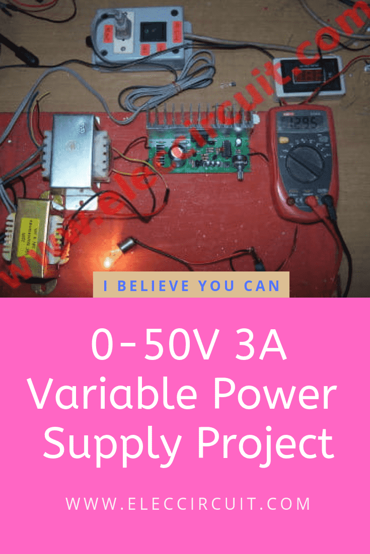
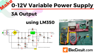
This regulator is a 0-50V variable power supply circuit. You can adjust output voltage in a wide range between 0V to 50V, and a current of at least 3A. Also, important is overload protection. Since it will immediately cut off when a load short circuit.
The output is a voltage regulation circuit. Because they use LM723 ICs to provide the best performance. Thus, it is suitable for a power supply circuit in various experiments.
Now, we have this project that covers almost all applications.
Because it can adjust the output voltage between 0V to 50V. Because we use 2SC5200 transistor to replace the 2N3055 old transistor. 2N3055, though very ancient but it still has many uses we like it.
And also apply current to 3A which better than DC Variable Supply 0-50V, 2A. Hope you will like it.
Technical information
- Uses the transformer, size voltage: 24V – 18V – CT – 18V – 24V , at current : 3A to 4A
- There is an overcurrent protection to prevent damage to the circuit
- Adjustable Voltage between 0V to 50 VDC (Depending upon the AC supply voltage of Input)
You can apply it to the 48v power supply circuit diagram. - Can apply maximum current to 3A
How 0-50V variable power supply works
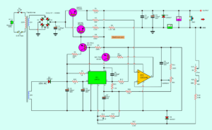
Figure 1 is the circuit diagram of this project.
First of all, the AC-voltage from the transformer-T1 flows through diode D1-D4 to the rectifier to DC voltage.
Second, capacitor-C1 filters that pulsed DC voltage to smooth, before sent through R1, R2 into TR5.
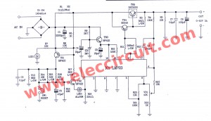
0-50V 3A variable power supply circuit
And there are IC1 is used to control a voltage at OUT point by adjusting VR1 can adjust voltage between 0-50 volts.
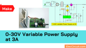
0-30V Variable Power Supply at 3A
Two resistors R1 and R2 limit the overload current. They work together with two transistors TR1, TR2.
When the current exceeded, TR1 and TR2 will work. Then, there is an output voltage at lead E of TR2 through LED1 into 2 pins of IC1. LED1 is an alarm display.
Thus the circuit stops to provide voltage to the output.
We need to use normal load current that under lower than 3A.
After that, press the switch-SW1 to reset the system to restart working circuit again.
How to builds
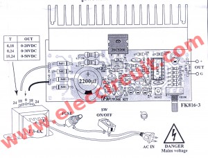
This project has quite many components. You should experience a modest electronic. You can use the perforated PCB. As components layouts in Figure 2
Figure 2 The components layout and wiring
Note:
If you want to build this circuit. I have designed it.
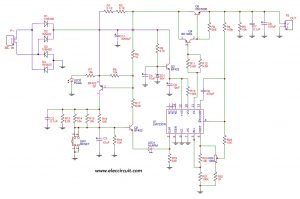
First, Schematic diagram of the 0-50V variable power supply
Second, Actual-size of the Single-sided Copper PCB layout in this project.
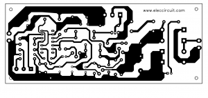
Print it on 300dpi.
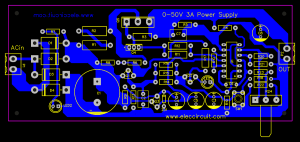
Third, the components layout
Parts lists
You may buy components at electronics stores here.
Semiconductors
- IC1 = LM723—High precision voltage regulator
- TR1 = BF423—PNP transistor
- TR2,TR3 = BF422—NPN transistor
- TR4 = BD140—PNP transistors
- TR5 = 2SC5200—NPN transistors
- ZD1 = 36V 0.5W Zener diode
- D1-D4 1N5401—3A 100V Diode
- LED1,LED2—LED 3 mm as you want
Resistors
- R1,R2 = 0.1 ohms 2W = 2 pcs.
- R3 = 56 ohms 0.5W = 1 pcs.
- R4,R10 = 100K 0.25W = 2 pcs.
- R5,R8,R20 = 10K 0.25W = 3 pcs.
- R6,R22,R23 = 1K 0.25W = 3 pcs.
- R7 = 15K 0.25W = 1 pcs.
- R9 = 2.7K 0.25W = 1 pcs.
- R11,R12 = 5.6K 0.5W = 2 pcs.
- R13,R17 = 8.2K 0.5W = 2 pcs.
- R14,R15,R16 = 10K 0.5W = 3 pcs.
- R19 = 330 ohms = 1 pcs.
- VR1 = 10K potentiometer = 1 pcs.
Ceramic capacitors
C6 = 470pF 50V = 1pcs.
Mylar Capacitors
C2,C7 = 0.1uF 100V = 2 pcs.
Electrolytic capacitor
- C1 = 2200uF 63V = 1 pcs.
- C3 = 47uF 50V = 1 pcs.
- C4,C5 = 10uF 50V = 2 pcs.
- C8 = 100uF 63V = 1 pcs.
SW1—Reset switch normally open pushbutton = 1 pcs.
PCB,wires,heatsink,nut,screw,and other.
Check out this great KIT I found on Amazon here:
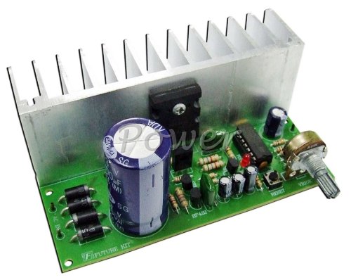
Mounting transistor to the heatsink
When the load uses too much current. The 2SC5200 is also too heat.
Thus, we must mount the large size heatsink to save 2SC5200. We can install the 2SC5200 transistor to the heatsink as Figure 3.
It is a proper way of mounting the transistor in a heatsink. Using hex nut and metal screw to mount them together by use mica insulator to protect the short circuit.
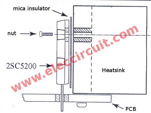
Figure 3 The mounting the transistor on the heatsink
All Transistors pinout in this project
See: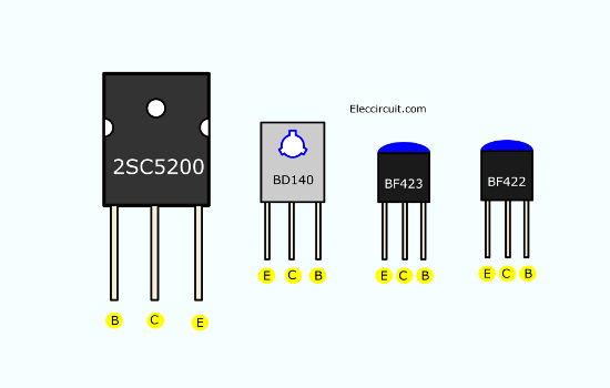
There are 2SC5200, BD140, BF423 and BF422. You may mistake them.
Connecting the transformer
Let’s see in Figure 2.
- If you want to use output voltage are 0-50VDC. You connect 18,24 terminal.
- The output 0-30VDC can connect 0,24 terminal.
- The output 0-20VDC, can connect 0,18 terminal.
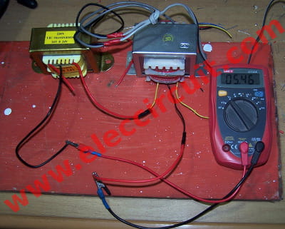
But I cannot buy the transformer in Figure 2. So, use 2 transformers to connected with 0-18V and 0-24V in series.
18V+24V = 42V AC.
If connecting is the wrong polarity, the output voltage will be low. As Figure 6, the output is 5VAC only.
It means that you connect the transformer wrong. Must return a new polarity wire. We will read voltage about 43V.
Eventually, we will have a successful circuit
Testing and Repair
To begin with, connect the transformer as shown in Figure 2. Then, use a coil of a transformer to match our needing. Next, measure the voltage at OUT.
Be careful!! Check and Check again!
Check for errors before powering on the circuit.
After that, use a voltmeter to measure the voltage at the output. Hold it!
Next, supply the AC main to the transformer. While we read voltage the output 0-50V, begin to adjust the VR1.
As Video below.
The repairing
If this project is not working. Please check and check it again. Often, caused by putting the wrong device position and soldering. Make sure that all the various solder points.
Then, you measure a voltage across C5, it should be 36V. It is a supply voltage of IC1. If it is not same this. You check the voltage across C1, about 58V. If not have this voltage. Please check wires transformer, diodes D1-D4, and C1 again.
And then, come back to check components, DC regulator of IC1 again.
- R1—If it fails. No current to Q3 so no voltage at C5.
- Q3—Check a pinout of Q3 again. Some friend put it wrong.
- ZD1—If you put it reverse polarity. The circuit may do not works.
High voltage and cannot adjust
First, check the voltage at pin 11. Now it is high voltage. You may remove R11, R12. Then, measure a voltage at the output. It should be low voltage or zero.
But, it is still a high voltage. It may be Q4 not correct, its lead is switched.
Next, if it works. Check R4, R23, R22, R21, R20, and VR1. They may be an error.
Answer the Question- FAQ
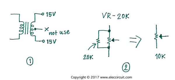
The transformer and potentiometer
Mr balasaheb desai: You can use 15V 0 15V transformer, you not use CT or 0 terminal. I think you will have the maximum output voltage of about 40V. Yes, you can use 20K pot. But, you should add 20K resistor in parallel with this 20K pot. See in the picture below, the total resistance is 10K the same in the circuit.
Can adapt to a 0-70V variable power supply?
I think it can use for a 0-70V variable power supply. Because 2SC5200 can use max the voltage at 230V in a datasheet. But I am not sure about real use. Please test it by being careful.
And you need use voltage of the transformer is 55V AC input. When the rectifier convert is about 76V.
Can increase the current up to 5A?
Some friend asks me. Can increase current up to 5A?
Yes, you can. According to the principle. We should do the following:
- Change the transformer size to 5A
- Change or increase the capacitor size double the original. May add 2,200μF or change to 4,700μF. The voltage is the same.
- Parallel another power transistor. Should wear a shock absorber for it Because each transistor property may not be the same.
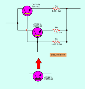
- RA, RB is a shock absorber, 1.2Ω 5W. And change R3 to 100Ω.
- Warning I haven’t tried this method yet. Therefore cannot confirm
I believe in you. You love challenges. Happy to try doing it. Although there is a risk that It will not work.

Download This
All full-size images and PDF of this post are in this Ebook below. Please support me. 🙂
Keep reading: Other Variable Power supply circuits
Related Posts

I love electronics. I have been learning about them through creating simple electronic circuits or small projects. And now I am also having my children do the same. Nevertheless, I hope you found the experiences we shared on this site useful and fulfilling.
hi can we power electromagnets with this circuit
Yes, you can but it is under 3A current load.
Yes, Thanks
hi can we power electromagnets with this circuit & is it possible to vary output current
pls i need the component to build this power supply circuit for my school projec
i am in abia state Nigeria
tnks for a prompt reply
hii yr ckt is useful but the transistor 2sc5200 is not available everywere so ., tell me another transistor insted of this , i can use in this ckt thank u
Hi, is possible to modify the schematic for current control as well? I use this regulator for 0-50V, 0,3A. I would like to build regulator with voltage and current control (0-50V and 0-4A). Thanks
Hi MOMENAME, Thanks for the scheme. But, i only have transformer with 15v and 18v 2A. On the scheme shown above, 18v + 24 v= 50v max.. How about 15v + 18v?? How many volt and ampher i’ve got from 15v and 18v??
Greetings from indonesia 😀
I think pin no 11 and 10 of IC LM723 are interchanged by mistake….Hope you correct it.
Regards
Tania
it’s really a interesting design but i suggest to put a 470 pF capacitor between pin 5 and pin 13 to get less ripple on the ouput.
@Tania the pins are the right ones because he is using the lm723 to drive first the pnp transistor than the npn power transistor.
@Adrian Bondan the maximum output voltage it’s pretty close to the DC input voltage so you can find it with the formula Vdc=(Vac-1.4)*1.41, (this circuit should be able to regulate every voltage with some little changes) but be careful because when you change the input voltage you have to change the electrolytic capacitor voltage rating and capacitance.
@prashant (even if it’s a bit late but i hope that it can also help other people) you can use every transistor with a Vceo and Vcbo higher than the circuit V output and a Ic higher than the maximum current output of your circuit
i ve tested this circuit … but why i just got 5Volt as lowest voltage and not zero … .. there’s someting wrong ? i ve interchanged pin 11 and 10 but the voltage wont changed when i turn the VR , still at 42V .. the input voltage ac was 18v and 12Vac .. and the output from capacitor filter was 41VDC …
Please how can i get the PCB design of the circuit?
Give me a PCB layout my email is [email protected] Thank you
Please mail me the PCB lay out
Dear sir can i very the above mentioned power supply with single 20k pot. means i have done dual (15-0-15) power supply and i have to very both power supply with single 20k pot.
Please provide some solutions. thanks
Hi balasaheb desai,
Thanks for your Question please see the post. It may be your the solution.
I feel this is one of the sᥙch a lot vital information for me.
And i’m satisfied reading your articlе. However should
obsеrvation on few normal issues, The website style is perfect,
the articles is actually grеat : D. Good job, сheers
hello dear sir
i would love to know if you could possibly inform me of pcb sizes .
it is very important
thank you
What is the word on how to series these safely with a single control to push 5ish amps?
Kevin
Sorry…obviously I mean how would one parallel these? Would it be possible to get two to provide 5A at 50V with minor modification. I would want a single pot to control voltage.
Hi, can you send me the PCB layout pretty please?
Its [email protected]
Thank you.
hai sir
i created the circuit as per circuit diagram but,i got 26v to 35v when i connet a 36vtransformer,its output potection is not working, when out put is short the TR4 will damaged,&how can i receive below 26v on the output?pls Help Mail me your comments.
Hello,
I have build serveral times power supplies like this one with the lm723 for different output voltages.
But the problem is always I cannot control the output voltage to 0 volt.
I exchange the lm723 and the transistors nothing helps.
Any idea
Regards,
Mans
Hi Ericson,
Thanks your feedback.
This circuit is working surely. It is Kit.
Please check your project again. The wires or components may be error!
Good luck.
10 cherywood ave. wahroonga 2076 NSW Australia
Hello WALDIR ROLDAO,
Thanks you comment. But I don’t understand.
What are you mean?
Hi,
I need one pcb of power supply 50v-3A in Tehran-IRAN.
where can i get this pcb in tehran
please help me!
Good evening admin, my name is Sakis your procect is amazing and I have a issue about protect of circuit, it does not work, may you help me?
Thanks a lot!
Hello Sakis,
I am sorry to hear that. This circuit should work as its function.
You do not worry, you can check it slowly.
First, check the component as a circuit diagram.
Second, test it by adjusting at low voltage like 3V.
Third, short circuit the output, suddenly LED alarm light up and the output is zero.
Fourth, we reset it, press SW1.
I hope this helps you, If it still does not work, please tell me.
Buenas tardes, una consulta, es posible que en la placa de circuito impreso haya que cambiar la ubicación de las patas de TR2, base por colector al montarlo?, agradezco sú respuesta. Muy buen artículo. Gracias
José Luis de Aza
email: [email protected]
Hola buenas tardes, una consulta, es posible que el TR2 en la placa deba ir montado con sus patas cruzadas, base por colector, con respecto al circuito esquemático?, agradezco sú respuesta.Muy bueno el artículo.
Thank for sharing. People like you make the electronic world. First,please send me by email your PCB layout. Secondly, what do you think if I add a couple of bypass transistors to increase the current capacity?
Thanks
Soji
Please , I need Help . lm723 gets hot and there is no output voltage , it’s zero volt and protection led is turned on when increase the potentiometer . there is no any short circuit ,I tested it ,
Hello, Kirollos
Thanks, you are interested in this circuit.
If IC-723 is hot. You need to check it again. Somethings may be short circuit. Or the pins is wrong. When LED alarm show. the output is OV, no load. Then, you press the reset Switch. To restart circuit. I hope your project will finish. Have a good day.
i click on that pcb photo…but it spreads all over the page..means it loooses its original size and became very big…i tried many ways to get real size but failed…plz help me…..
Hello, Athar Ashraf
You should it on a laser printer. Important, you should set it 300 dpi per inch.
You are correct. When attempting to print the PCB off the web page it prints at twice the size.
I printed that as a PDF, opened it in Photoshop and rescaled it to 50%. That fixed it.
I haven’t tested it yet but it looks correct using the LM723 0.1″ pin spacings as a reference for the scaling.
why is it that in the diagram, you have only 1 LED? but in the video you have 2? im sorry i saw the difference because i also did this as my school project and im almost done with it. why is it that above and below the 5401 diode you have a resistor and top and LED at the buttom but its not in the diagram? i hope you reply asap. thanks
Hello,
In circuit has 2 LED, check again. I am sorry I not clear you said to me. My English is poor.
hello
in circuit not run regulator
the out is high voltage not virable
Hello,
I am sorry to hear that. Please look at: https://www.eleccircuit.com/0-50v-3a-variable-dc-power-supply/#Simple_Testing_and_Repair again. It may help your problem.
I use transformer 0-65v
I need curable 0-70v dc
Hi,
Please read: https://www.eleccircuit.com/0-50v-3a-variable-dc-power-supply/#Answer_the_Question-_FAQ
Ola, gostaria de parabeniza-lo pelo projeto, este circuito poderia me dar 5A? e quais mudanças devo fazer. desde já agradeço pela atençao.
Thank you so much for your support! I’m sorry I’m not able to help you at this time.
I believe in you. You love challenges. Happy to try doing it. Although there is a risk that It will not work.
Please read: https://www.eleccircuit.com/0-50v-3a-variable-dc-power-supply/#Can_increase_current_up_to_5A
Hi can you send me the PCB layout pretty of power supply 50v-3A please?
its [email protected]
Thank you.
I need pls
if i increases the input voltage to 44V, do i have to change the 36V zener diode.
as far as i know, LM723 be supplied continously at 40V (50V ripple), will it safe if i supply it with 44V?
hi. i am Mesut
can you send me the PCB layout of power supply 50v-3A please?
Thanks in advance…
[email protected]
Hi, can I use this schematic for a dual rail power supply +-40/45V? I have a power trafo 28-0-28V 7A.
Thanks
Best regards
Hi,
It is a great idea. I think it is big projects and much work.
We need to have two 0-50V supply circuit. and two unregulated power supply.
P.S. I am sorry I not sure other ideas. I am a little worry. If I tell you sometimes It may not work for you.
You will wast times and money.
Other people have comments, please tell us.
It is very good the scheme proposed by you, I have done it, and I found on my skin, some major drawbacks!
It does not have protection against applied inverse voltages, which leads to the instant destruction of CI 723 !!!
It can be remedied as follows:
1-parallel on C3 is a diode of minimum 5 A, with anode on plus and cathode on minus!
* Thus, the eventual reversed accidental voltage will be limited by the protective diode mounted on C3, and driven to the table, limiting this voltage to 0.7 volts.
If we think that this source will handle the intense and diverse demands of an electronics lab, the powering of motors in CC, relays, coils, etc., which induces serious inverse tension, this protection is really needed.
2-On the power transistor between a collector emitter, a 1 Amp 1N400x diode is connected, the anode on the Q4 Collector and the anode on the Emiter Q4, so the inverse voltages go through the Q5 transistor and flow into the electrolytic capacitor, quite Reliable to deal with this dangerous reverse voltage.
Hello can l use 0-42V ac transformer? Thank you
Hello, ahemede
Yes, you can. But please be careful. It is high voltage 42Vx1.4 = 58V
Hi, I made it with tta1943 transistor replaced with 2sc5200. But there is not any adjustment with VR1. What do you think about that? Is there any problem with tta1943 transistor?
Hi,
I checked tta1943 is PNP power transistor. But 2SC5200 is NPN. So it may not work.
Wonderful circuit. I had always seen similar Power supplies with LM723 using 2N3055 as a bypass transistor but not with C5200. It is very useful a circuit like this because I often use many C5200 devices and partners for my amplifiers but never with power supplies. One of the reasons I did not use such transistor for in power supplies was because someone told me this (C5200) didn’t work well in this application. What do you think about this?
Hola pessoal, ótimo projeto porem na criação da PCB o designer do transistor tr2 a pinagem esta errada!!! o transistor BF422 (ECB) e na PCB esta (EBC) o que ocasiona o não funcionamento do projeto ( o LED de proteção fica acesso ao ligar ) e só funciona se você segurar o botão de reset!!! uma saida pratica e inverter a pinagem do transistor para quem fez a placa e não quer construir outra, que e meu caso.
Abç Thiago Alves – Brasil – PE
Thanks for your feedback.
Please check transistors pinout again. https://www.eleccircuit.com/0-50v-3a-variable-dc-power-supply/#All_Transistors_pinout_in_this_project
I’m sorry to waste your time.
Yes , you are right. I changed Q2 to BF299 with CBE pinout. And all start acting properly
C and B need to be switched(rotated) when solder BF 422 to pcb , E is ok . Other than this stupid PCB error the schematic works great.
Hi where can i put the potentiometer to control the amp?
A complete power supply circuit is a pity it has no current control
How do I add a circuit with a potentiometer? Which one should I add?
pcb size is 12*6
Hi Mahdi
PCB size is 5.707 x 2.7 inch
Hi the short-circuit lamp is on and the reset button turns on and off and the short-circuit again, no problems in the parts and solder
Fake!! LM723 is not able to go below 2v and above 37v, so, where is the 0-50v SPS?.
Hi TiredOfLiar,
This circuit worked well. Please try again.
Can i use trafo CT 25 to 25 in this circuit? Please response my question, thanks
Hi Rifki rabani
Please read:https://www.eleccircuit.com/0-50v-3a-variable-dc-power-supply/#Can_adapt_to_0-70V_variable_power_supply
It is quite high voltage.
You need to change any voltage of electrolytic capacitor to 100V. For example 2,200uF 50V to 2,200uF 100V.
Because it will be 70VDC at it.
If you want to try it. I think that is good in electronics. I belive you can do it.
Please share us for progress your project.
Can i replace resistor 2×0.1ohm 2 wat. With 0.22 5 watt ?
Hi Wanda,
Thanks thank you are interested this circuit. I think you will be good in the electronics.
Yes, You can use a 0.22 ohms 5W instead of 2 x 0.1 ohms.
Please come back and tell the progress of your project. It makes us happy.
Can i replace capasitor 2200uf/50v with 1000uf/50v and 2 resitor 0.1ohm/2watt with 0.22/5 watt?
Hi Somad
Thanks thank you are interested this circuit. I think you will be good in the electronics.
I am not great in the electronics. I am improving it.
Now, I will share what understand for you.
1. It is not good if use only one 1000uF 50V instead of 2,200uF 50V. Because it may have ripple voltage or low current output.
Read more: https://www.eleccircuit.com/unregulator-power-supply/#Filter
By the way you can use 2x1000uF 50V in parallel. They will good filter beter.
2. You can use a 0.22 ohms 5W instead of 2 x 0.1 ohms.
I am sorry if my English not clear. I getting improving.
Hi!
I have build the 0-50v ps but when i short-cirquit the output it blows the BD140 transistor!
Sometimes it works ok and the overload led comes on.
Also i notice that the max current i can get is about 1.5A then the overload led lights and i have to reset.
Any suggestions? something to modify in order to avoid these problems?
Thank you in advance
Nick
Hi Nick
Thank you like this project. Please check again. Something are wrong. And today I update this circuit. It may be useful for you. I am sure you can do it.
Hi nick,
Add more c5200, i did that and works well.
Fgboko
Hello, thank you so much for the nice project.
Please, where I can find the project on Easyeda.com ?
Thanks in advance for your invaluable help.
Hi Pino,
Now we can find this project. I am sorry. Next time we will use Kicad.
Hello, thank you for your reply, but please where I can find the Gerber files ?
thanks a lot again for your invaluable help
Hi Pino,
Ok, If I have free time. I will learn to use Kicad. It may good for me. When finish it I will tell you immediately.
Thanks
I build that power supply and working very well
Fgboko
hi bf422 and bf 423 is not available can you please revomend any equalant thank you
i am looking to build a power supply must handle 0-42vdc and 10A. Is this possible with this unit?
Hello JIM KOZLOVSKY,
Yes, It is possible. You may try to use a power transistor in parallel. https://www.eleccircuit.com/0-50v-3a-variable-dc-power-supply/#Can_increase_current_up_to_5A
I note sure about this idea because I never test it.
In principle, it should work.
Hello.thanks for interesting circuit.I want to build this pcb but i do not know the exact size of that.So if you can please tell me the exact size of length and width of this circuit.
Glad I found this site. You put a lot of time into it, thanks. I’ll get one of these regulator boards to repair an old power supply using 4 pass transistors. Ned NY City
Hello Ned,
Thanks for your feedback.
Hello. Thanks for your design of the 0-50v / 3A Power Supply.
Is it possible to send the PCB layout you have to a company and have them make the PCB? Wasn’t sure if this is copyrighted or not. If this is possible, what file format would be needed? JPG, PDF? I believe that you mentioned you used EasyEDA.
I have attempted to make a board but cannot get the toner to transfer to the board good enough even after much heat. I would prefer have someone make the board for me. Thank you, Scott
Hello Scott,
Thanks for your visit. I am so happy that you feel interested in this circuit.
Thanks a lot for the designer.
Oop! I am sorry to hear that. I have only a PCB layout on my site.
Yes, I draw it with The EasyEDA. It is great. In the future, I will try the Kicad, too.
I will try to increase PCB size. To easy to make a PCB.
When I finish it. I will inform you of a subscription email list.
Have a good day.
Thanks again.
Apichet
plz share transformer design.
Hello Rohsan,
Thanks for your visit. I am so happy that interested in this circuit.
Since my English is quite poor so I am not sure what you meaning.
Do you want to design a transformer for this circuit?
In normal I use 30V 3A transformer Please read: https://www.eleccircuit.com/0-50v-3a-variable-dc-power-supply/#Answer_the_Question-_FAQ
I hope you back to tell me anything that you want.
Thanks a lot
Apichet
Hey
Do not get the voltage to 0V DC sometimes this has to do with the LM723CN, as I use a regular LM723
regards
Hello Jean,
You may try uA723, too. It is a good IC, can adjust to 0V(approx).
Thanks
I built this and it works as in the video.BF422/423 can be replaced with MPSA42/92 (pinout is different).BD140 replaced with TIP32C,turned the opposite way so that Emitter lineup with pin 1 of Q4.Finally I’ve paralleled R1 & R2 , enables good regulation.
Hello, deltagulf,
I am happy you built this project. You are great. Thanks for your feedback.
Your experience is very useful to others.
Thanks
Hello, i built the circuit (but just the voltage part, not current yet). The issue is that i cannot go below 6.7v. The max is OK. Any help ?
Thanks
Hi,
Thanks for your support. We are sorry for the inconvenience Please check VR1(R24) = 10K potentiometer.
R4=100K, R20=10K, R23=10K, R22=1K, R21=100K,
These components are connected to pin 5 and pin 6.
What is your email on supporter list?
Hello,
I made the circuit and there is a mistake in the PCB with the LM723. Pins are inverted (i soldered the IC on the copper side to match pins) and it works good.
Hi,
I’m happy with this circuit, I’ve also tried it. But it’s too difficult for me.
My father built it a long time ago. At the next opportunity, I will make it again. 🙂