Today we will learn about the basics of the capacitor time constant, or RC time constant. It refers to the constant time required for a capacitor in an RC circuit to charge or discharge.
The RC time constant is one of the main properties of an RC circuit, as well as being fundamental to many electronic circuits. And today we will understand what the RC time constant is and some of its usage examples.
This article builds on our previous capacitor-related articles, including What Is a Capacitor: Types and Working Principle and Properties of Capacitors in Series and Parallel. However, because this topic is not particularly difficult, we believe we will have a clear understanding by the end of it.
Charge and Energy in Capacitors
First, let’s do a quick recap on capacitors. They store charge within them using an electric field, which can be defined using the following formula.

Where Q is the amount of charge in units of coulombs, C is the capacitance measured in farads, and V represents the voltage.
Then we can convert these values into E energy (in joules) stored within a capacitor using this formula.

This energy the capacitor stores would not be converted into heat like a resistor and will eventually return to the circuit. Also, the energy is insignificant compared to what is stored within a battery; thus, a capacitor cannot effectively function as an energy source.
RC Circuit
The capacitor (C) in the circuit below is charged from the voltage source (Vs), with the current flowing through the resistor (R). Hence, the circuit is called an RC (resistor-capacitor) circuit.
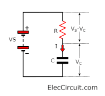
The voltage across the capacitor (Vc) is zero at the beginning but will increase as the capacitor starts to charge. We can say that the initial charge current is Ohm’s Law of

As the capacitor is being charged, the charge current (I) is determined by the voltage across the resistor over its resistance,

This means that as Vc rises, the voltage across the resistor (Vs – Vc) decreases, which causes the charge current (I) to decrease as well. Therefore, the capacitor charging rate will continually decrease as it is being charged.
Capacitor Time Constant
What is the time constant for an RC circuit? Simply put, it is the measurement of the time that the capacitor charges with the current through the resistor. The time constant is defined with this simple formula.

Where the time constant (τ, lower case Tau) has units of seconds (s), R is the resistor’s resistance with units of ohms (Ω), and C is the capacitor’s capacitance with units of Farads (F).
Considering the example circuit below, the time constant is the period from turning on S1 to C1 voltage reaching about 63.2% of the battery voltage. We will shortly explain where that 63.2% came from.
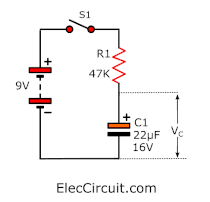
Using the time constant formula earlier yields

Since the time constant in an RC circuit is the product of resistance and capacitance, a high time constant implies a high value for either resistance or capacitance or both. This likewise means that the time constant does not depend on the capacitor alone but also on the resistor.
Charging
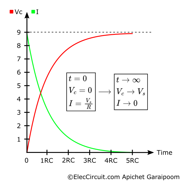
The time constant (RC) for charging the capacitor is the time it takes for current (I) to fall to 1/e (≈36.8%) and voltage (Vc) to rise to 1-e^-1 (≈63.2%) of their initial value.
Both values have a direct correlation; as voltage increases, current decreases. In other words, current has exponential decay, whereas voltage has exponential growth, as seen in the graph below.
It can also be expressed using

and,

Where the e multiplier is the rate of change per time constant.
After 5RC, the current has already fallen to less than 1% of its initial value. At this point, we could say that the capacitor is fully charged; however, in theory, a minuscule amount of current will continue to flow indefinitely.
Plotting the Vc data from the graph into a table roughly shows that the voltage (Vc) and the charge (Q) rise very quickly at first. But when the current decreases, the rate at which the voltage increases also goes down.
| Time (t) | Voltage (Vc) | Charge (Q) |
|---|---|---|
| 0RC | 0.0V | 0% |
| 1RC | 5.7V | 63% |
| 2RC | 7.8V | 86% |
| 3RC | 8.6V | 95% |
| 4RC | 8.8V | 98% |
| 5RC | 8.9V | 99% |
Discharging
When the capacitor discharges, both current and voltage fall at the same rate of 1/e (≈36.8%) of their initial value. The voltage discharged from the capacitor is translated into current, and the charge also has a direct connection to the voltage.

This time, both the voltage and the current decrease at the same exponential decay rate, as shown in the graph below.
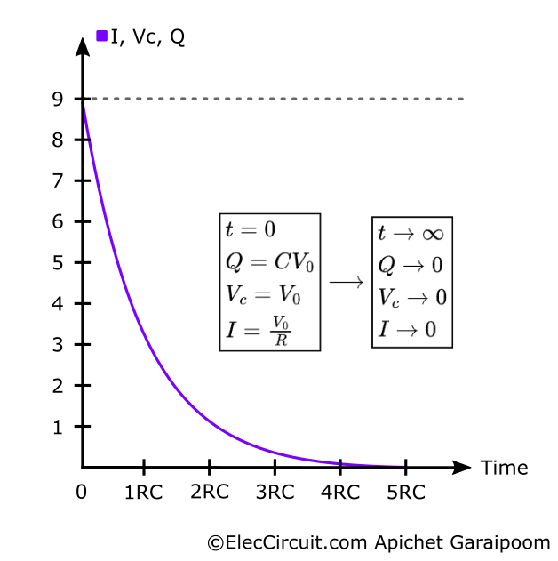
All these three values have the same exponential decay formulas of

The current will initially be very high because of the high voltage, but as the charge runs out, the voltage decreases rapidly, and so does the current. As the charge and the voltage deplete, the current also decreases, which means that the rate of discharging becomes lower and lower.
The table below illustrates this point by plotting the voltage and charge approximately.
| Time (t) | Voltage (Vc) | Charge (Q) |
|---|---|---|
| 0RC | 9.0V | 100% |
| 1RC | 3.3V | 37% |
| 2RC | 1.2V | 14% |
| 3RC | 0.4V | 5% |
| 4RC | 0.2V | 2% |
| 5RC | 0.1V | 1% |
After the fifth time constant (5RC), the voltage across the capacitor is effectively zero, and we can say the capacitor is completely discharged. But of course, there will be a tiny amount of current flowing long after this point.
Example Circuit That Utilizes RC Time Constant
We often use the capacitor time constant as a form of time delay, but here are a few example circuits to help us understand its usage better.
Simple Speaker Turn-on Delay Circuit
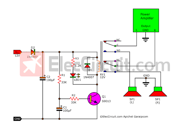
The RC circuit is composed of C1 and R1. It will delay Q1 from working for about 3 seconds before letting it function properly. Read more about this Simple Speaker Turn-on Delay Circuit.
Basic Power-on Delay with RC Time Constant
In the figure below, the RC circuit consists of R1 and C1 parallel to each other. The whole circuit still uses the charge and discharge operation of capacitor C1.
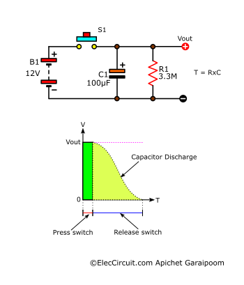
The moment we press switch S1, capacitor C1 is rapidly charged. Thus, the Vout is equal to the Vin of 12V. When we release the switch, C1 slowly discharges through R1 until it is empty. Similarly, the Vout gradually decreases to 0V.
The time of this discharge is calculated using t = R × C.
The Vout should only be connected to a load with a high impedance to avoid shortening the time value. If the load has a low impedance, it is like connecting another low-resistance resistor in parallel to R1, causing the value of R to go down.
Using Buffer to Fix Problems with Time-Constant
A buffer, as shown below, easily solves the problem of external components affecting the time constant we had above.
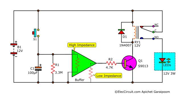
In this case, the buffer functions to match the RC time constant high-impedance output with the transistor circuit with low-impedance input. You can read more about this concept here: https://www.eleccircuit.com/power-off-delay-timer/
Simple Delay Circuit using Darlington Transistor
This circuit is relatively simple. When S2 is pressed and released, LED2 will light up for about 30 minutes or so.
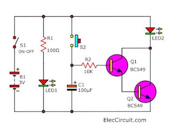
C1 determines the time (t). Similar to a buffer, the input of the Darlington transistors (Q1 and Q2) and R2 has a high impedance, which does not affect the time value.
Using MOSFET as a Buffer
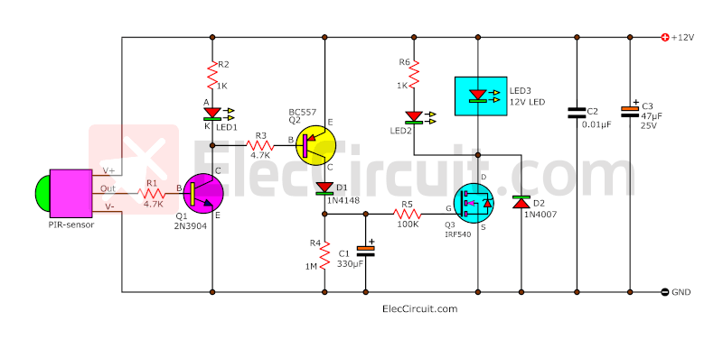
Another interesting circuit uses a MOSFET instead of a transistor because its input impedance is very high, which is ideal for an RC time constant. Thus, we could save on some components since MOSFETs work as well as transistors and relays.
Another thing is that we use Q2 instead of the switch we used in the previous example circuit, which makes it more convenient. You can read more about it here: https://www.eleccircuit.com/simple-automatic-motion-sensor-light-circuit/
These are just some of the many examples of the capacitor time constant. The main application we see uses basic capacitors’ charging and discharging principles.
Conclusion
The capacitor time constant in an RC circuit is a relatively simple and essential topic in electronics that sometimes gets overlooked. It is a core part of many timer or time delay circuits, yet it comprises two of the most common components: a capacitor and a resistor.
If you are interested in reading more about capacitors, we do have a few other articles talking about such topics. You can check them out here:
- Control timing —for example, used with IC timer 555 to control charging and discharging
- Smoothing —for example, in the power supply
- Coupling —-for example, connecting the audio system and speakers
- Filtering — for example, in the bass-treble tuning circuit of the audio system
- Tuning — for example, in a radio system
- Store energy —for example, in circuits, flashes, cameras
Download This
All full-size images of this post as PDF are in Ebook. Thanks, support. 🙂
GET UPDATE VIA EMAIL
I always try to make Electronics Learning Easy.

I love electronics. I have been learning about them through creating simple electronic circuits or small projects. And now I am also having my children do the same. Nevertheless, I hope you found the experiences we shared on this site useful and fulfilling.
Adorei e gostei muito, mas muito mesmo,sobre este Tutorial ( Usos de Capacitores) Grato.
Hi Antonio Rodrigues Brandão
Thanks for your feedback.