There are many simple electronic tricks and tips. To do Electronics in an easy way.
Although it is not the best. But I believe It is one step of learning. To increase electronic skills.
DIY AC Ammeter from multimeter
A general cheap analog multimeter will not have directly AC current ranges. But we are an Electric Appliance Repair, will always have this problem. For example: Measuring current of the electric appliances.
How to modify our meter?
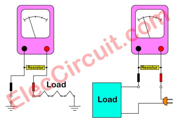
We can modify the multimeter on AC 10V range to measure AC current 0-10A, use a 1 ohms resistors in pallial to lead of meter.
The resistor must withstand power (watts) is adequate, do not burn while measuring.
How to find the power of resistors.
The current of the circuit squared then multiply by 2, to the safety of its use. The current value is about 2A is a resistor value that is equal to 8 watts (2x2x2).
Add to that the resistor will measure current less than 10A. Which is the highest on the scale? If you want to measure more than this to reduce the resistance to the other.
While the measure has to be careful not to resistors in parallel, then dropped it. Otherwise, the meter will be damaged
How to use a Battery Tester
A basic electronic learning what is needed is a battery. Because I do not want him to use the AC-line, which could be dangerous.
So we store it in a lot of batteries.
Sometimes project electronic does not work well, may have caused Batteries broken, or worn out…should be replaced.
Normally, I tend to use the digital multimeter measure its voltage. But it’s convenient to have too many batteries.
Son and I saw the battery tester.
my son tried to use it, very convenient. He can make it easy to use the 1.5V battery of all size(AAA,AA,D and more) and the 9volts battery.
Battery Size :
1.5V , Good = 1.5V-1.28V ; Low power = 1.27V-1.15V ; Replace = Before = 1.15V
9V , Good = 9V-7.8V ; Low power = 7.7V-6V ; Replace = Before = 6V
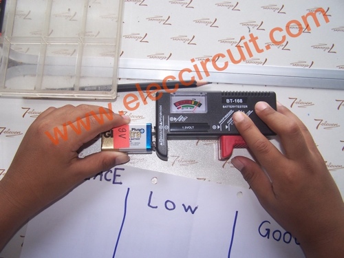
If friends interested to buy it, you may like it same us.
DIY Make Solderless Flexible Breadboard Jumper Wires
DIY Make Solderless Flexible Breadboard Jumper Wires
A jumper wires in the experiment electronic circuits labs on Breadboard is indispensable. Normally we can buy them from general electronic store. Which is cheaper as amazon.com
Solderless Flexible Breadboard Jumper Wires M/M 100 pcs at www.amazon.com
Now, I will tech my son to make them before. To apply more thing to make tools or projects for save and DIY life.
We have fully devices
1. We have a lot of flexible wire, 24 – 30AWG
Figure 1
2. Heat-shrink tubing 3 mm.
Figure 2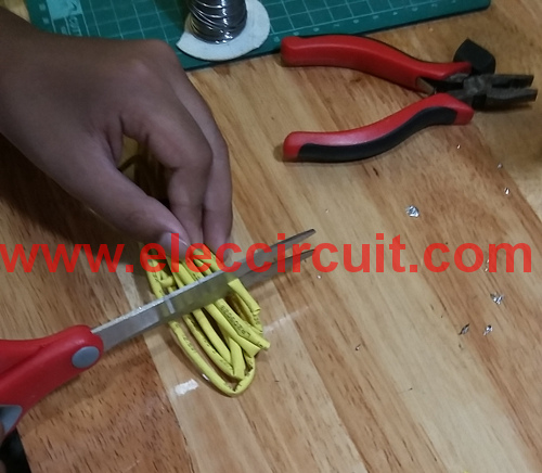
3. Office pins about 0.5mm
Figure 3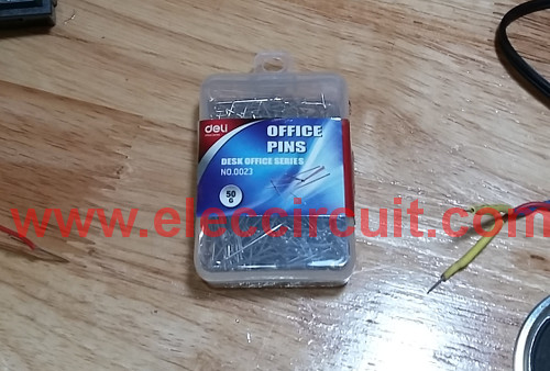
How to make its
My son cut the wires for 5-10 cm. Then, strip the insulation from the ends of two pieces of 22-gauge flexible wire go out.
Next,joint the copper wires to the pins as Figure 4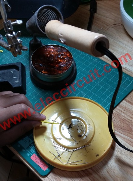
And then,he solder to the joint as Figure 5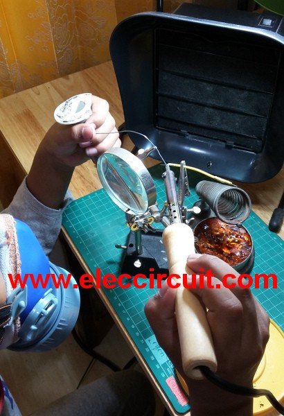
Next, cut nail heads of the pins as Figure 6 because the Nail heads are large, embossed.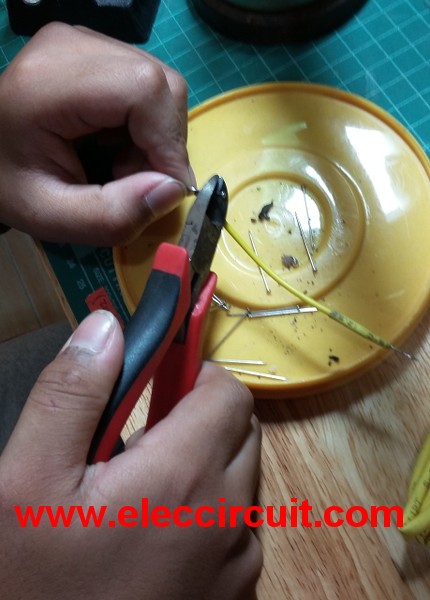
Cut the Heat-shrink tubing is 1.5cm, then Slide the tubing along until the joint is centered under the pins as Figure 7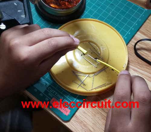
Then, use heat gun to apply to the tubing,leave the heat on the tubing until it shrinks to firmly cover the joint. As Figure 8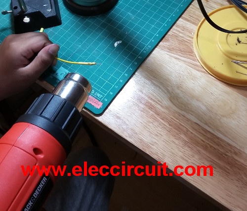
As soon as the tubing is tight around the wire, your job is done as Figure 9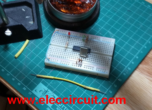
Test the his Solderless Flexible Breadboard Jumper Wires as Figure 10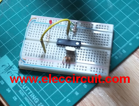
He is happy his job and make microcontroller project so well.
How to fix unclear the 7 segments led display
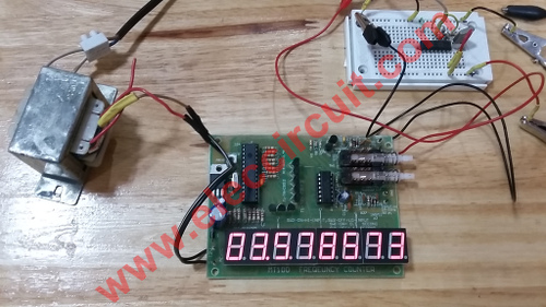
I’ve bought cheap digital frequency counter kits. It works great, can measure frequency up to 1GHZ in 19$ only. It uses 8 the LED 7 segment display. But it’s a little brighter so cannot clearly read the value.
My son fix unclear the 7 segment LED display by Installation film Cars. Makes Digits display very clear.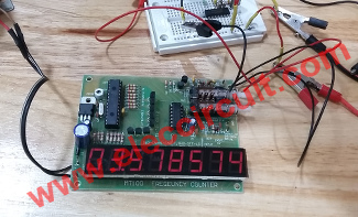
Figure 2 Digits clear when use film
How to make easy
This films, He request the car store near the house. Select the intensity level of about 60%.
First of all,
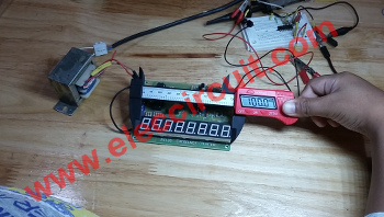
Figure 3 Measure the width the LEDs
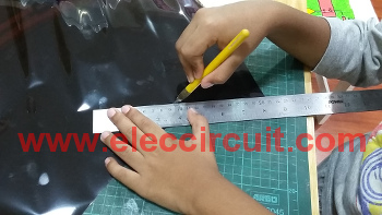
Figure 4 Cutting the film to size LED display
Then, Apply the films on the LED display
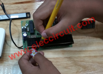
Figure 5 Trim the film to good look
This is a simple tip that my son uses it. We do not need to modify it in the circuit. We can do it, good luck.
How to build the PCB by yourself
Creating a PCB is difficult. If you want to create your own PCB.
I find good information on various websites. For the benefit of friends.
This week, I collaborated with Xander to show you how to make your own printed circuit boards (PCBs) using a laserjet printer.
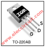
We should use IRF540N HEXFET Power MOSFET
An IRF540N is HEXFET Power MOSFET that I like to use in many projects. It is very Fast Switching than general transistor.
When I compare it with a transistors that I like to use is a TIP41. It have IC ( collector current) about 2A and VCE( collector-emitter voltage) about 40V only.
You can buy the IRF540N on amazon. It is N-channel that same way as shape NPN transistor TO-220 package. But they have Drain current maximum about 27A-33A and Vdss (drain -source voltage) about 100V.
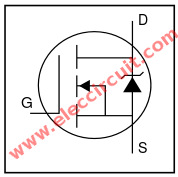
IRF540N N-channel HEXFET Symbol
Another advantage that I like it, works with a voltage. High input impedance therefore very sensitive. So we can be parallel directly, D to D, S to S and G to G. By we do not need to increase current to G.
Thus,If the price of of similar We should use Mosfet better.
Preliminary Technical specification.
– Advanced Process Technology
– Ultra Low On-Resistance
– Dynamic dv/dt Rating
– 175°C Operating Temperature
– Fully Avalanche Rated
I like the use of the brand International Rectifier durability due And for good reason.
More electronic projects using it worked great!
Simple resistive load
This is simple resistive load,Sometimes we need to use a resistors that without capacitance or inductance. We always use the carbon resistors. But some working to need the resistor that has also many high power. Which we cannot use the carbon resistor because it has maximum power about 2 watts only.
Normally, performance testing of amplifiers need to apply low resistance load and not affect the frequency. That is pure resistance requirements and The normally power amplifiers have also have high power. (Several hundred watts)
Alternative way is to change the resistor into the wire wound model. This resistor tolerance is very high. Because structure is a wire with a high resistance on the ceramic core. The problem is the inductance hidden inside. Which is caused by winding wire is coiled itself.
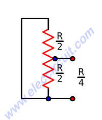
Figure 1 Simple resistive load
If as the DC circuit this lower inductance, no problem. But for working with high-frequency circuit will result in a lot.
The solution is connects the circuit as Figure 1. The current flow in resistor will opposite and cancel out. However, the total resistance has been reduced from the original.
Assuming the value of R, but was divided into two parts. Each section is equal to R / 2 and when the two parts are connected in parallel and be left with impedance R / 4.
This resistor can connects to point out the resistor is (tap). Which currently may be hard to find. But there is another way Using conventional 2-wire resistor with a resistance equal to the parallel instead. But do not forget to consider the resistance forces and the resistance of the circuit is required.
Make Lamp as power load
We like to test the functionality of a high current power supply by simple power load. It is 12V lamp 50 watts. But it had a high temperature. Require a docking station proper on long time trials.
Today my son build docking for this lamp.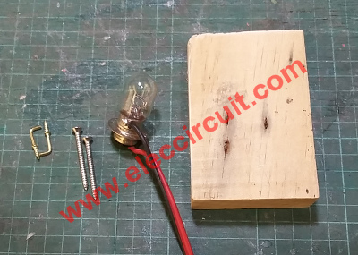
Figure 1 All parts
We use:
– Light bulb
– Metal screw 2 inch
– brass hooks as terminals
– Thick wooden planks
We use Incandescent motorcycle head light bulbs 12V 25W/25W without a head light socket
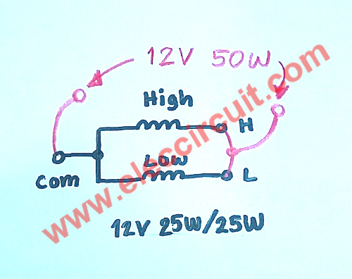
Figure 2 The structure inside light bulb
The structure inside light bulb has two filaments for the high beam and low beam filaments are soldered two parallel, it would have a combined 50 watts as Figure 3.
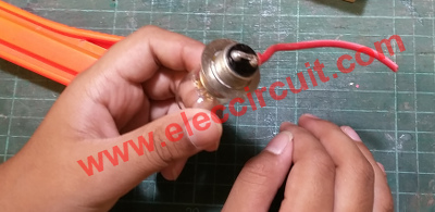
Figure 3 Both Filament are soldered together
Then, install screws and the brass hooks on planks as Figure 4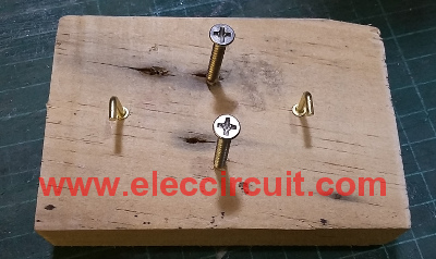
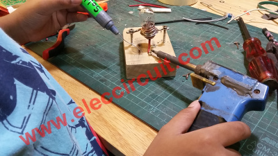
Figure 5; We install the screws and the brass hooks onto the planks are finished.
It is technically simple electronic If you are experiencing similar problems. Get lucky.
Computer Tips
Irfanview:
Use the mouse wheel to zoom in and out.
- Holding CTRL key while using scroll wheel will zoom in and out.
- SHIFT + CTRL will show a zoomed area around the mouse pointer.
Cr:https://www.reddit.com/r/IrfanView/comments/10mhk5u/how_do_i_use_my_mouse_wheel_to_zoom_in_and_out/?rdt=53365

I love electronics. I have been learning about them through creating simple electronic circuits or small projects. And now I am also having my children do the same. Nevertheless, I hope you found the experiences we shared on this site useful and fulfilling.


Thanks.
Hi,Salim Khan,
You are welcome.
hallo,
danke für den tipp.muss manchmal den strom von waschmachinen messen…..
viele grüße…..
Hi,walter
Thanks for your feedback.
Please type in English because I am not understand you say.
Would The Power Rating of the 1 ohm resistor be 100 watts?? P=IxE= 10A x10V=100watts and P=IxIxR=10x10x1=100watts??? Is This Right???use 1v scale Power would be 10 watts???
@momename…..Thanks for the Tip//Sometimes I must measure the Electricity of the Washing machine.My German is Very Weak but I provided Everybody with a rough Translation..I know only about 300 words in German..Hope This Helps,,Bye For Now!!! PS* I Love This Sit…THANK YOU!!!!
I Love This Site!! OOPS!!!
Hi, Mr OHM 1970.
Thank a lot for your feedback.
You can also rotate a bridge rectifier and place a DC current meter between the + and – output terminals of the bridge, and connect the AC input terminals in series to the load. Just make sure the start current of the appliance doesn’t greatly exceed the meter rating.