This is the Infrared Remote control transmitter circuit. It has high performance and can be applied to works with the various infrared receiver circuit. To made easily and best to save your money.
I want not to tell you much, what is the infrared remote control. Because you have known as well. So I recommend circuits 2 types, as appropriate.
- The first is a simple circuit. The Infrared light from a section to a section to work immediately.
- Then other circuits are designed to have wider applications. They can be set programs of a beam of infrared light to circuits.
Let’s get started.
The basic infrared remote control transmitter
Usually, when we apply a DC voltage to the infrared diode. It works but we cannot see the beam light with the naked eye.
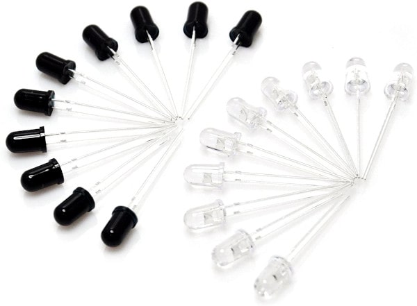
You can find this infrared LED on Amazon here if you’re interested.
But in real applications, we need to power it with a pulse signal at a frequency of about 5kHz. Because of eliminating the various noise and reduce the power supplied to them.
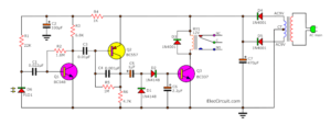
See in the first circuits. It is a simple infrared transmitter circuit using 555 timers. We use it as It is an oscillator generator at a frequency of 5kHz. that is set with R1, R2 and C2.
The output signal will have a period on-off is 1:1 or we called 50% duty cycle.
The resistor R3 is used to limit current flow through the infrared diode under 50mA.
Improved circuits
Previously, I used this circuit, but Mihai introduced new device configuration principles. I agree And thank you for the useful advice. We should improve the circuit.
- We want a LED, gets the current average approx 50mA. If we use a 9V battery at 68 ohms, it uses current about 132mA. And if the output is a square wave 50% duty cycle. So, the current of LED is 60mA (approx).
- Change C1 is 0.0033uF for output about 5kHz.
The shopping list
- IC1: 555 timer
- R1: 3.9K
- R2: 47K
- C1: 100uF 16V Electrolytic
- C2: 0.0033uF 50V Ceramic
- C3: 0.01uF 50V Ceramic
- Infrared LED
- B1: 9V battery Or 9V regulator circuit
It is short! Do you want a far infrared light?
Recommended: How does a SCR thyristor work?
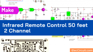
The high infrared transmitter circuit
We think easily, add 3 infrared LEDs. Sure, It lights up and shines afar. But the previous circuit cannot drive them full power. We need a helper. We know a transistor is a best friend, easy and cheaper.
So, we add it to the circuit.
Here is a high power infrared transmitter circuit. See below.
Also, the 555 is used to generate a square wave frequency, about 5kHz. This frequency is determined by the VR1, R1, R2, and C1. We can adjust VR1 to change frequency, too.
The Output of IC comes to the base of transistor Q1, BD137 to drive infrared diodes with high current to 100mA. Resistors R3 is limiting the current resistor for infrared LEDs. It should not be less than 3.9 ohms to protect the damage of that infrared LED and Q1.
And R4 and LED1 indicate that the power-on of the circuit.
But…this circuit has a mistake. Colin Mitchell Said, this circuit is dangerous. It is true.
Even I love to collect a lot of circuits. Sure, some circuits may be wrong. I admit it. And, I will fix it as soon as possible, however, that mistakes are part of learning. And will always develop.
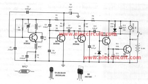
Improve High infrared transmitter
Anyway, we will learn it See the update version, below. He suggested this as follows.
The voltage drop across each of the infrared LED is about 1.5V to 1.9V.
The output of this is maximum of 6V.
When the transistor is turned ON, the voltage across the 5.6 ohms can be up to 6v.
The current through the 5R6 can be as high as 6/5.6 = 1amp !!
Most infrared LEDs work well, between 30mA to 100mA. So, the circuit may damage them.
How to improve it
By adding 1 more component, the output driver transistor can be converted into a CONSTANT CURRENT device.
And the current set by the value of R4 to suit the IR LEDs. This will deliver the same current for a supply voltage from less than 9v to 12v or slightly more.
Thank a lot Teacher. Read more
Not only that, See third circuit too.
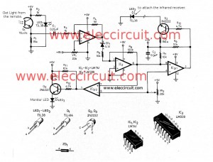
Small Infrared transmitters circuit using LM3909
This is an infrared transmitters signal circuit that is small size and using a power supply 1.5V only. The main electronic parts are two the LM3909 (a LED Flasher Oscillator IC.
We often use it as a simple flashing light circuit. Using a 1.5V low power supply, it’s working.
Now, Easier to use transistors, too. The high frequency, it is very simple, just change the device to the high-frequency only. Both C1 and R1 set a low-high frequency at the output.
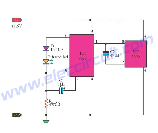
Small Infrared transmitters circuit using LM3909
NOTE
This circuit is very useful. To study the infrared light transmission circuit. But if you actually try to experiment. Please study more details. Also, read the commerce below. Thank you a lot.

Related Posts

I love electronics. I have been learning about them through creating simple electronic circuits or small projects. And now I am also having my children do the same. Nevertheless, I hope you found the experiences we shared on this site useful and fulfilling.
Be aware that the current through IR LED is limited to about 136mA(if R3=68Ω) and not 50mA. The usual term for the “signal period on-off” is called “DUTY CYCLE” and in this case is about 0.52 or 52%. Anyway, this duty cycle is too much. Try to lower it, say 10% or less. It’s good for the LEDs.
What formula did you use to compute the output frequency? With those values the frequency is about 3.13Hz(the period is 0.3189sec). In order to obtain the desired freq.(5kHz) you should use 3nF(0.003µF) for C2 instead of 4.7µF.
Now, for the second diagram…
…R3 should not be less than 3.9 ohm… I think you meant R4!
You don’t need an electrolytic cap. for C2. A poliester cap will do the job brilliantly. R1 should be no less than 5kΩ. 470Ω is way too low. Check the application note AN170 regarding NE555 for a proper design. Like that one above, the duty cycle is too much(>50%). Lowering the duty cycle while maintaining the frequency unchanged will reduce the power consumption. In
this instance R4(5.6Ω) dissipates around 8Watt, so BEWARE!!!
Wonderful web site…great projects …keep it up!