This infrared remote control can control the working of 2 channels or can use to control two Electric appliances, each one on-off freely and a maximum of 300 watts on Control distance is 50 feet.
How does it work
We will describe the operation of this project into two parts: a transmitter and a receiver.
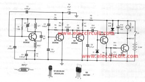
Figure 1 is a Transmission.
An IC3/1 act as generated a frequency channel first, and an IC3/2 for a channel second 2.
The IC3/3 and IC3/4 act as generated frequency about 40 MHZ, which is a carrier wave frequency.
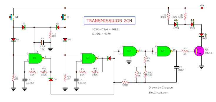
Figure 1
When press switch CH1 or CH2, The frequency IC3/1 or IC3/2 is mixed together with the carrier frequency, then sent to TR1 to increase out of LED-infrared output which our eyes can not see.
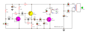
And Figure 2 is an operation of the receiver section. First of all, a module receiver will is derived from the signal from LED infrared.
Then, decoder tone signals out of an out point. Next is sent to C6 and C14 into pin 3 of IC1 and IC2, IC1.
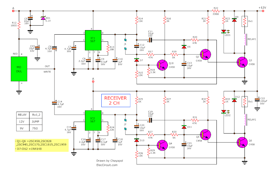
Figure 2
The IC2 will check a frequency signal that reaches if this frequency match with frequency at IC1 or IC2. The voltage at pin 8 of IC1 or IC2 also will be “0” in normal states that IC still not works at pin 8 of IC.
The frequency source is set to both ICs depends on R and C value at pin 5 and pin 6. After that IC1 or IC2 worked will send the signal to a control relay section.
Both relay controllers have a similar operation, so will describe just one section.
When IC1 runs will be sent into the relay controller circuit, which has the operation alike the flip-flops circuit, is on-off as we press switches at the transmission
Assume at pin 8 of IC1 is “0” so pull the voltage at the base of TR1 through a C12-capacitor and D7-diode, so makes collector lead at TR1 has high voltage through R19 to base lead of TR2, causes TR2 works and as a result, TR3 works with LED1 glow and relay1 pull in.
When there are pressing switches at remote again, at pin 8 of IC1 will be “0” again, so pull voltage to the base of TR2 through C11 and D8, thus makes TR2 no conduct current, and TR3 not works and relay1 stop as the same time LED1 goes out, at collector lead of TR2 so has high voltage or “1” then the current flow through R15 to the base of TR1, cause TR1 to come back to works again.
Recommended: How does a SCR thyristor work?
How to assemble circuits
The Circuit assembly on the PCB as Figure 3 is Transmission and Figure 5. is the receiver section and relay controller section. Should solder a small device before, such as Resistors, Diode, ICs, capacitors, relays, and LEDs. Then inspect error before test this circuit.
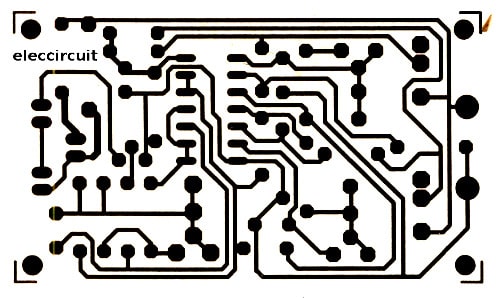
Figure 3 Single-sided Copper PCB layout of transmission.
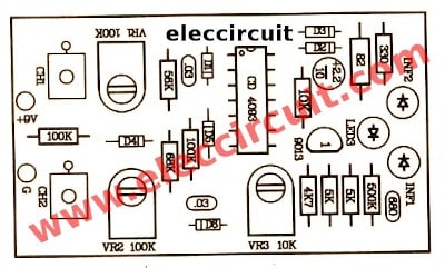
Figure 4 the components layout.
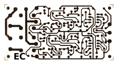
Figure 5 The copper PCB layout of the receiver section
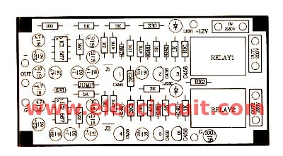
Figure 6 The components layout.
Testing and Tuning
Connecting circuit as Figure 7 but do not apply AC220V to them. Then apply the 9V power supply to the relay controller circuit.
Next, insert the 9-volts battery to the transmission.
Then try to press switch CH1 to hold on, just LED1 at remote transmission will glow, then turns LED-infrared to Module receiver.
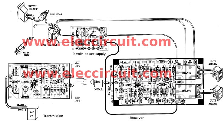
Figure 7 the application of this project
Then adjust VR3 to the middle position, Then partially Adjust – VR1 until LED1 glow, next press CH1 again. The LED1 will light with relay works.
Next, adjust CH2 by press switch at CH2 then partially adjust VR2 to LED2 glow. After that tuning both channels.
If press remote then cannot receiver so adjust VR3 to increase Distance received – sent about 10-15 meters.
Experiments on such results, connect the AC-220V to IN-220V at Out1-220V and Out2-220V is provided for connecting an appliance to be controlled.
If the distance is not more than 8 meters do not need to have all 3 lenses.
Most parts list
TR1-TR6 = NPN transistor : C458,C828,C945,C1740,C1815,C1959
D7-D12 = 1N4148 – 75V 150mA Diodes.
Note:
The jumper is used to select Relay voltage in each channel. Example 12V relay you short Rx1 together and then 9V relay you use 75 ohms-resistors across between both polarity.
J1 and J2 to set the type of switch-mode when pressing the remote. If connected with wire will be normally pushbutton switch. Then if we opened J1 and J2 will be an ON-OFF switch as control remote.
GET UPDATE VIA EMAIL
I always try to make Electronics Learning Easy.

I love electronics. I have been learning about them through creating simple electronic circuits or small projects. And now I am also having my children do the same. Nevertheless, I hope you found the experiences we shared on this site useful and fulfilling.

what are the measurements of PC layout and the components layout
The PCB layout image. You need to print it on 300 dpi. If your project work please share me.