This simple digital voltmeter circuit diagram is a saving, easy to use Because it is smaller than a typical circuit, I believe that after I presented this circuit. You will certainly like it.
Note: Also this you can see these projects:
This circuit can be used as Versatile. Features of the circuit :
– 3-digit numeric display with LED 7 segment.
– The maximum display +999 mV and the maximum negative-99mV.
– Adjustment measurement range is not limited by the resistance, only two options.
– Using the voltage + 5 V single power supply is not necessary to use the negative circuit pack.
The heart in the working of circuit is IC CA3162E. Which converts analog signals into digital signals in a Dual – slope A / D conversion.
The output of IC will be the multi-plex binary code display type. so easy to build because has the wire to the display is a few.
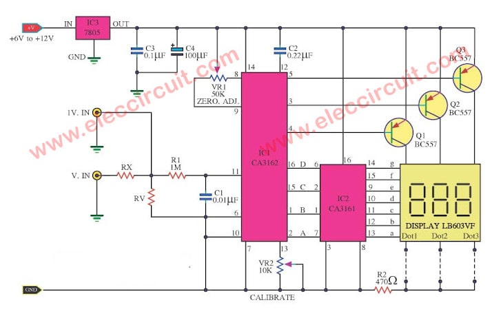
For the input signal we are divided into two ways to be:
First: 1V.IN for measure the DCVolt that has a voltage not exceeding 1volt.
Second: But for those who want to measure the voltage higher than 1V. Enter the inputs into the Vi point, and change the Rx,Ry as you want.
For example : you would like to the measure rang a maximum of 99.9 Volt you should use the value of Rx=10M, Ry=100K
And in the the measure rang of 999V you should use the Rx=10M and Ry= 10K etc.
OR …..
The Ry may be calculated from the formula:
Ry = 10,000,000 /(Ei-1)
When the Rx = 10M is fixed.
Ei : is the measure rang as you want.
C2 is a integrating Capacitor.
The parts of this circuit
IC1: CA3162E, A/D converter for 3-digit display
IC2: CA3161, BCD to Seven Segment Decoder-Driver
Q1, Q2, Q3: BC548, 45V 100mA NPN Transistor
0.25W Resistors, tolerance: 5%
R1: 1M
R2: 470 ohms
Rx: see text
Ry: See text such as: 100K at 100V
VR1: 50K, Trimpot 18T
VR2: 10K, Trimpot 18T
Polyester Capacitor
C1: 0.01uF 63V
C2: 0.22uF 63V
C3: 0.1uF 63V
C4: 100uF 25V Electrolytic Capacitors
Display: See in circuit.
How to build this project
First of all we make the PCB and placing all components as Figure 3. What to look carefully for is the polarity of the electrolytic capacitors and Diodes, led 7 segment display correctly. Pin of the IC is not an error.
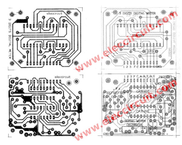
Figure 3 the PCB and components layouts of this projects.
Customization, you should have a reference voltage and the digital voltmeter in successful. To compare measurements. And then…
VR1 for adjust the ZERO ADJ , VR2 for adjust the CALIBRATE of the circuit.
This circuit is designed for use with the power supply 6V to 12V by it has the IC3-uA7805 to be the DC voltage regulator 5volt.
Digital voltmeter circuit »
GET UPDATE VIA EMAIL
I always try to make Electronics Learning Easy.
Related Posts


I love electronics. I have been learning about them through creating simple electronic circuits or small projects. And now I am also having my children do the same. Nevertheless, I hope you found the experiences we shared on this site useful and fulfilling.