If you are looking for a dual power supply rectifier circuit that uses only one secondary coil.
We have many ways to use it. Today we recommend two good circuits.
But these circuits are suitable for a low current load only.
Otherwise, it has too much ripple voltage or noise.
Are you up for it?
First Circuit# Dual 6V Power supply
Look at the circuit below. It is so easy dual power supply circuit. We can get +6V and -6V of output at current about 50mA.
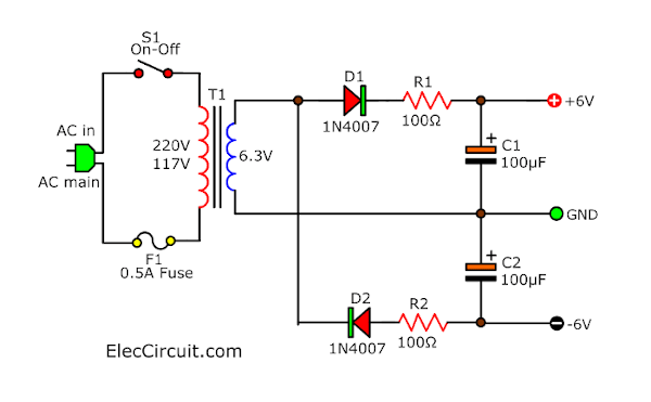
If your load requires dual voltage positive, negative and ground like OP-AMP circuits. You can try this circuit.
We placed both resistors to reduce a ripple voltage or small noise.
This circuit is an Unregulated power supply that uses a half-wave rectifier. It is easy but not good for all. Why?
Read next: Learn Half-wave rectifier on a DC supply
Parts you will need
- T1: 6.3V, 0.1A secondary transformer
- D1,D2: 1N4002 Diodes
- C1,C2: 100uF 16V Electrolytic capacitors
- R1, R2: 150 ohms 0.5W Resistors
Dual supply with Two Bridge version
Warning
This is Simple ideas for power supply. It has the certainty of damage due to accidental short circuits. Please very very be careful a lot.
Thanks a lot : observerms, Scott
It will convert any AC signal to DC unregulated voltage. In the circuit below, we use 2 bridge diodes and 4 electrolytic capacitors.
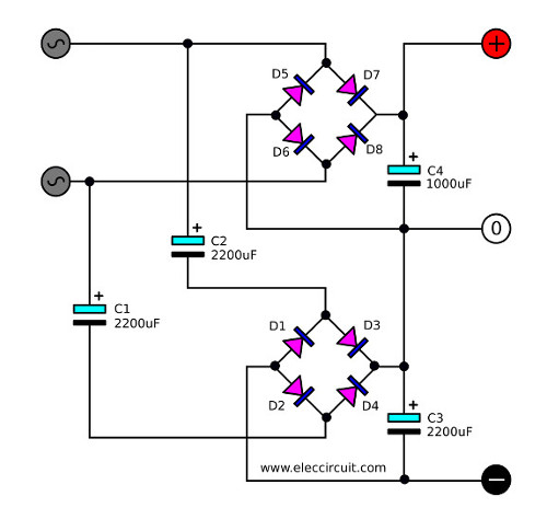
The first section is the normal mode. Which it includes first bridge diodes (D5 through D8) they act as full-wave rectifies ACV to DCV.
Then, a capacitor C4 will filter the pulsating DC into a steady direct current (DC).
The second section. Also, the AC signal from the input will flow to C1 and C2 to the Bridge rectifier (D1 through D4)
Then, the current flow to filter the pulsating DC voltage of out others bridge diode of the transformer. It causes us can connect directly the positive of 0 volts. Thus, the output will be symmetric both positive and negative.
And since C3 is charged by impedance higher than C4. Because of the value of C1 and C2. Thus, the value of C3 so must be more than C4, to cause a ripple of DC voltage symmetrical both positive and negative.
Not only that You can look other power supplies: Learn more
The voltage of the capacitors must be the same maximum AC voltage of the transformer. In the circuit, use 15V at the external current is 0.1A cause a ripple voltage of 1V.
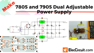
More Dual power supply rectifier circuits
If you need to have a low ripple voltage than this. We must use more capacitance of all capacitors.
While we must use the voltage and the current rate of the diode to higher than the power transformer and the load.
Parts you will need
D1-D8 = 1N4007- 1000V 1A Diodes
C1,C2 = 2,200uF 35V Electrolytic Capacitors
C3,C4 = 1,000uF 35V Electrolytic Capacitors
Check out these related articles, too:
- Multiples ways to increase the power supply current
- Power Supply Splitter circuit using op-amp
- 12V Dual Power Supply using 7812, 7912
GET UPDATE VIA EMAIL
I always try to make Electronics Learning Easy.
Related Posts

I love electronics. I have been learning about them through creating simple electronic circuits or small projects. And now I am also having my children do the same. Nevertheless, I hope you found the experiences we shared on this site useful and fulfilling.
Please, concerning thiis topic dual power supply using a two terminal transformer,can I also use it for high power amplifier like all those professional amplifier and slaves up to 70v supply?
Ups sefty
I know it’s really old post but I have to say the thanks for design , its really simple but incredibly effective
would u please help me about that, how to get dual power using single terminal transformer with only two diods.
Hi, Shohan
Thanks for your question.
Please see the text. I add a simple Dual voltage supply circuit with 2 diodes for you.
Is it right?
Simple ideas for a power supply should include a warning about the CERTAINTY off damage due to accidental short circuits when using this design.
Hello observerms,
Thanks a lot. Your advice is very good.
I hope you will come to advise us again.
I don’t believe your “Dual supply with Two Bridge version” will work. The bridge rectifier for the negative voltage it appears will conduct current through it and on to and through the positive rectifier rather than through the GND and – legs (i.e., the negative regulator chip or transistors). Result: burn up the negative bridge rectifier.
Hello Scott,
Oh … I must thank you very much.
You really explain how this circuit works in detail.
I learned a new. I believe that learning by mistake is a good way to learn.
Thank you for your kindness once again.
does not work alright ! do not try it the transformer will burn up it buzzed badly when i tried it