If you like to listen to nice music at your home. And you like to build electronic projects. You may like this. It is the 50w MOSFET amplifier circuit using 2SK1058 & 2SJ162.
Even if you’ve built this 50W Main Amplifier using transistor and IC.
But this circuit is better. The power of sound in low frequency is great. Also, It is easy to build, and very inexpensive.
Also, use Power Supply +35V -35V at 5A(stereo). Power MOSFET 2SK1058 & 2SJ162 must be mounted on enough heatsink.
We can directly connect it to CD players, tuners and MP3 player.
If you want a good amplifier, at affordable prices, for you to enjoy at home.
I recommend this circuit. Which has excellent sound quality. It is not lost other expensive sound system.
See spec below.
Features of the circuit
- Power output at 1kHz
- Load 8 ohm 50W
- Load 4 ohm 88W
- Power bandwidth +/- 1dB 20-50,000Hz
- Frequency response +/- 1dB 20-50,000Hz
- THD 20Hz-20kHz UP to rate power 0.05%
- Slew rate 20V/ microSec.
- Damping factor better than 50
- Signal to noise ratio 88dB.
- Input voltage for maximum 100mV.
How 50w MOSFET amplifier circuit works
See the circuit below. We will see that it is similar to a general MOSFET audio amplifier. Except for the output power MOSFET.
Instead, we use 2SJ49 and 2SK134. Which are more old, expensive and not necessary.
We use dual output Power MOSFET 2SJ162 and 2SK1058. Cheap much more. And other features, not less than any.
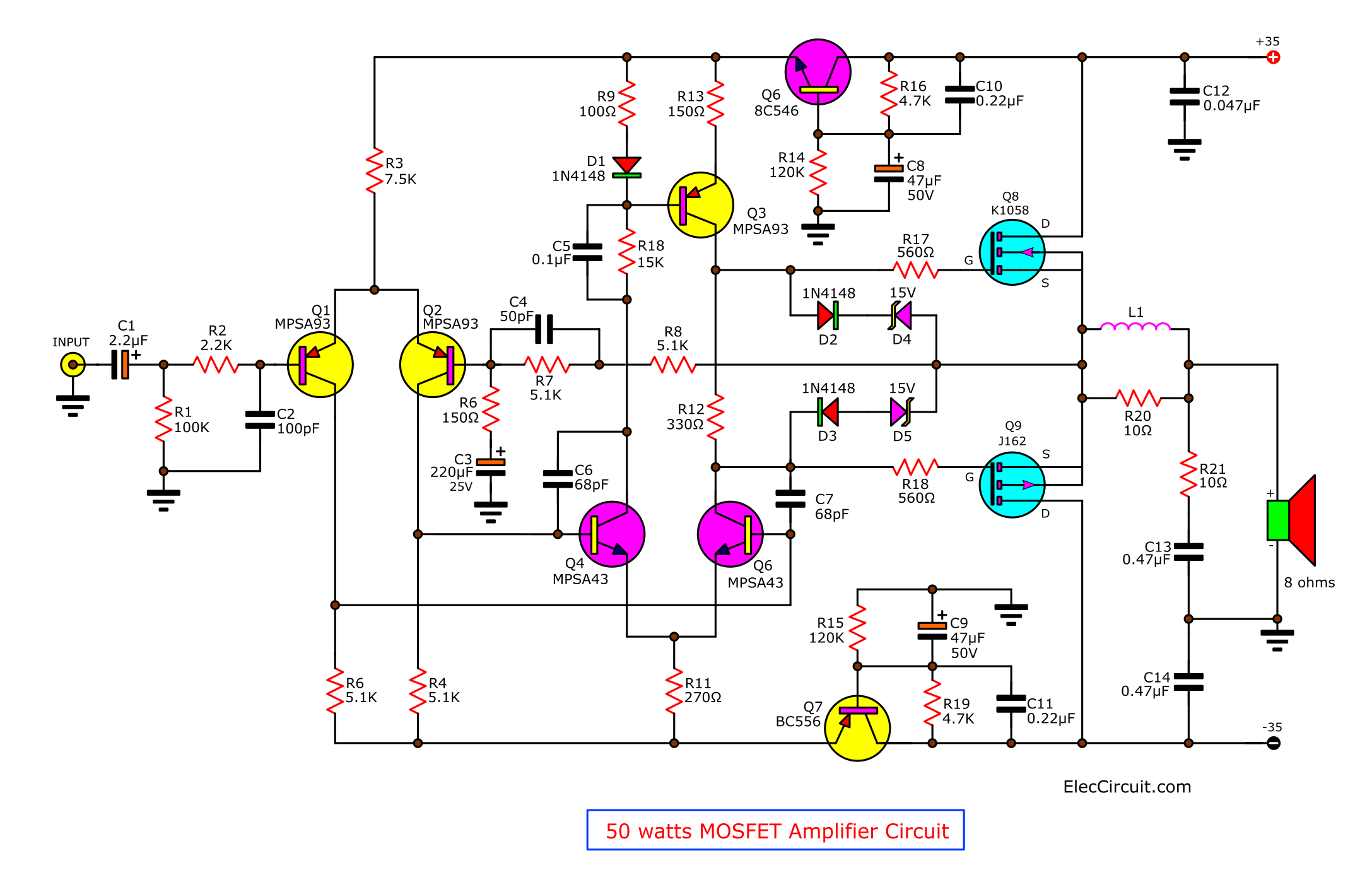
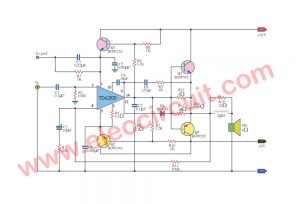
See Circuit diagram of 50 watts OCL Power Amplifier using 2SK1058 + 2SJ162
Also, the results from this circuit, it is the high-frequency response to better than output Power MOSFET J49/K134.
The operation of the circuit
The input signal is entered to C1 pass through a low pass filter circuit, R2, C2.
Then, to the differential input circuit, Q1(MPSA93), Q2(MPSA93) to Q4(MPSA43), Q5(MPSA43).
They act to amplifier an input signal to the Input signal to be strong enough to drive the gate of the output MOSFET. (Q8, Q9).
Then, the diodes, D1, D2, D3, D4, and D5. They are a protection circuit to prevent the too higher voltage to the gate of the MOSFET.
It may cause damage to the power MOSFET.
Recommended: High MOSFET Power Amplifier
Next, both transistors Q6 (BC546) and Q7(BC556) control the voltage that power to the driver section.
To not change follow the swing of the power supply. While we turn on the power to high.
This will also prevent noise that feedback to from the power supply wires. So, to reduce the noise of the circuit as well.
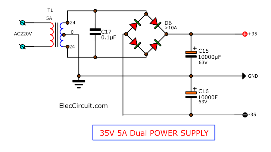
The power supply
This circuit requires enough power supply circuit. We use the 35V 5A Dual power supply circuit below. It is easy and uses a few parts.
You may like them, too.
- 12V Car Audio amplifier circuit 50W-65W
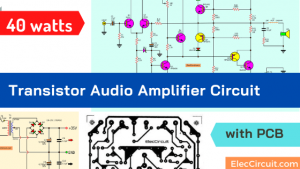
- 40W transistor audio amplifier circuit with PC
- 108+ Power amplifier circuit diagram with PCB layout
How to build
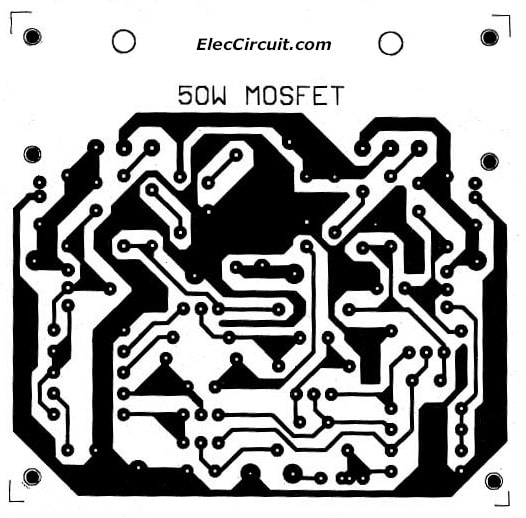
This circuit is very easy to make. Because it is designed in the PCB module. To reduce oscillation from the wiring at legs of MOSFETs is too long.
See the PCB layout below
And see the component layout below
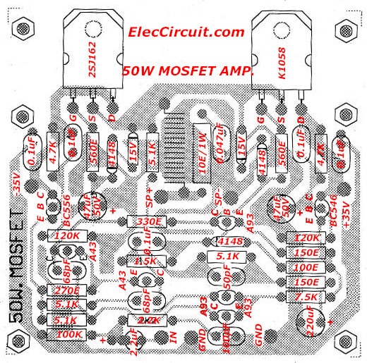
Therefore, every piece of equipment. Including the power MOSFET and the heatsink. They are designed to install on the PCB. as shown in figure above.
The Shopping lists
0.5W Resistors, tolerance: 1%
R1: 100K
R2: 2.2K
R3: 7.5K
R4, R5, R7, R8: 5.1K
R6, R13: 150 ohms
R9: 100 ohms
R10: 15K
R11: 270 ohms
R12: 330 ohms
R14, R15: 120K
R16, R19: 4.7K
R17, R18: 560 ohms
R20, R21: 10 ohms 1 watts
Electrolytic Capacitors
C1: 2.2µF 50V
C3: 220µF 25V
C8, C9: 47uF 50V
Metalized polypropylene capacitors or Ceramic
C2: 100pF 50V
C4: 50pF 50V
C5: 0.1uF 63V
C6, C7: 68pF 50V
C10, C11: 0.22uF 50V
C12, C13, C14: 0.047uF 50V
Semiconductors
D1, D2, D3: 1N4148, 75V 150mA Diodes
D4, D5: 15V 0.5W Zener Diodes
Q1, Q2, Q3: MPSA93
Q4, Q5: MPSA43
Q6: BC546, 60V 0.1A, NPN TO-92 Transistor
Q7: BC556, 60V 0.1A, PNP TO-92 Transistor
Q8: 2SK1058
Q9: 2SJ162
In creating, So just connects devices to form correctly. And Be careful soldering point to the closest. No Short circuit between that soldering points.
Check the output MOSFET that inserts the mica insulation. Is good enough or not?
Using Ohmmeter measurement. To make sure not short circuit or Short to the heat sink.
When testing all done, until sure is good to successfully. So, the trial connected the voltage of the power supply to the circuit to work right away.
Source: Pk Kit circuit Or…
See Here: 50 watts MOSFET Amplifier circuit
Note :
This project has a PCB amplifier is ready to build. You can view other projects.
Click here : Audio Amplifier(with PCB)
Note:
If you think that This power amplifier circuit is not good enough. For your work. It is hard to find parts.
You do not have it now. These circuits may be viewed below. It may be appropriate for you.
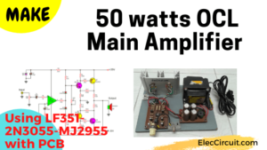
- Main Amplifier 50W OCL
- First POWER MOSFET Amplifier Project
- 100 watts Transistor Amplifier Circuit (OTL)
- Cheap 100W transistor power amplifier (OCL)
GET UPDATE VIA EMAIL
I always try to make Electronics Learning Easy.
Related Posts

I love electronics. I have been learning about them through creating simple electronic circuits or small projects. And now I am also having my children do the same. Nevertheless, I hope you found the experiences we shared on this site useful and fulfilling.
I have a question.
In circuit is shown that 10ohm resistor is paralel with coil and another 10 ohm resistor comes from C13 but on pcb is not like that?
In circuit are also 473 capacitors, on the pcb are 104.
And there is no data for L1.
Can you please explain.
Maksimiljan
excuse me mister Maksmilijan, have you ever figured out the value of the L1 in the schematic diagram? thank you!
Hi,
I have a question:
I want to use separate power supply for each channel.So the transformer must be 2 x 24 /2A.
That is write?
Thanks!
what is the disadvantage of setting quiescent current very low.
excuse me mister Maksmilijan, have you ever figured out the value of the L1 in the schematic diagram? thank you!
L1 must have 10 turns of 1mm wire in the shape of a pen.
I liked the way explained