Imagine you listen to a good audio system. When looking inside them. There are TL084 circuits as JFET Input Op-amps. Why should we use them?

TL084CN is low noise OP-AMP in cheap. Its input is JFET so high impedance. There is a Quad operational amplifier in one packet like LM324 or LM339. But they are different, that JFET input.
Even more importantly. Because of the BIFET technology make it well. There are wide bandwidths and fast slew rates. And have a low input bias currents, input offset and supply currents.
Are you a beginner? Learn Basic Electronics
TL084 Datasheet
When we learn about electronics with any circuits. We not should believe that circuit in 100%. I find information about that in many ways.
Check datasheet is the first way. Although I do not like to read too many texts. I love a lot of circuits.
Are you same me?
I will make it as short as possible.
Cr: photo TL084 from FlyNoval You can buy here.
Feature
- High Input Impedance: 10,000,000,000,000 ohms
- Input offset voltage options of 6.0 mV and 15 mV Max.
- Low input Bias Current: 30pA
- Low Input Offset Current: 5.0pA
- Wide Gain Bandwidth: 4.0 MHz
- High Slew Rate: 13V/uS
- Low Supply Current: 1.4mA per Amplifier
Maximum Ratings
- Positive Supply voltage: VCC = +18V (Recommend +5V to +15V)
- Negative Supply voltage: VSS = -18V (Recommend -5V to -15V)
- Differential Input Voltage (VID): +/-30V
- Input Voltage Range(VIDR): +/- 15V
- Power Dissipation (PD): 680mW
- Operating Ambient Temperature Range (TA): 0 to +70C
- Storage Temperature Range (Tstg): -65 to +150C
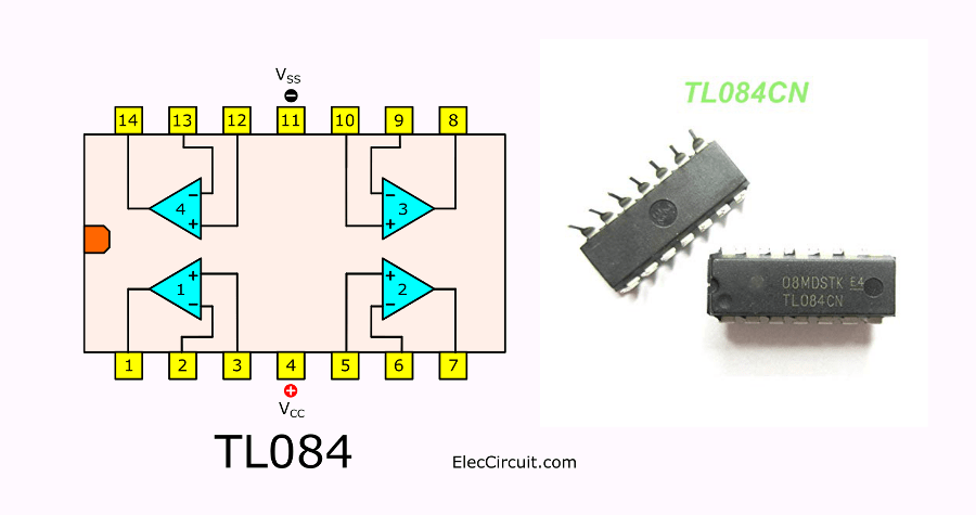
TL084 Pinout
Look above is TL084 pinout and pin connection inside them. You can use only one, two op-amp section. But should connect all unused input to ground. To reduce noise.
3 Example TL084 circuits in use
They are good preamplifier because of very high gain and bandwidth. Let me show you three circuits using TL084 as a base. Even it is so easy but they are useful.
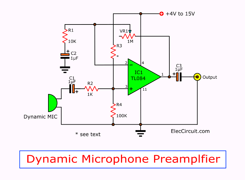
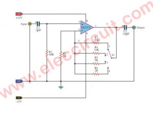
1. Low Dynamic Microphone preamplifier
See in the circuit. It has a few components. We will use TL084 as a dynamic Microphone preamplifier circuit.
How it works
Here is a NON-Inverting Amplifier. It’s more convenient when to use a single power supply, 4V to 15V. Because both resistors R3, R4 connect together in voltage divider form. And Capacitors coupling an audio signal.
MIC1 gets any sounds to convert to an audio signal. C1 passes that signal through R2 to non-inverting input pin 3. We use R1 and VR1 to control the gain of this circuit. Gain = 1+ (VR1/R1). So, we can control the gain by VR1.
We can use low or medium impedance Dynamic Microphone to this circuit.
Components lists
IC1: TL084 JFET input OP-AMP
0.25W Resistors, tolerance 5%
R1: 10K
R2: 1K
R3, R4: 100K
VR1: 1M Potentimeter
C1,C2: 1uF 50V Electrotytic capacitor
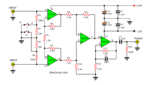
2. Low-Z Microphone Preamplifier
This circuit is low impedance(low-z) Dynamic microphone preamplifier. It is interesting. Because it is so small, a few parts.
The circuit form is direct coupling to reduce noise without capacitor coupling. So, use dual power supply, positive and negative voltage supply.
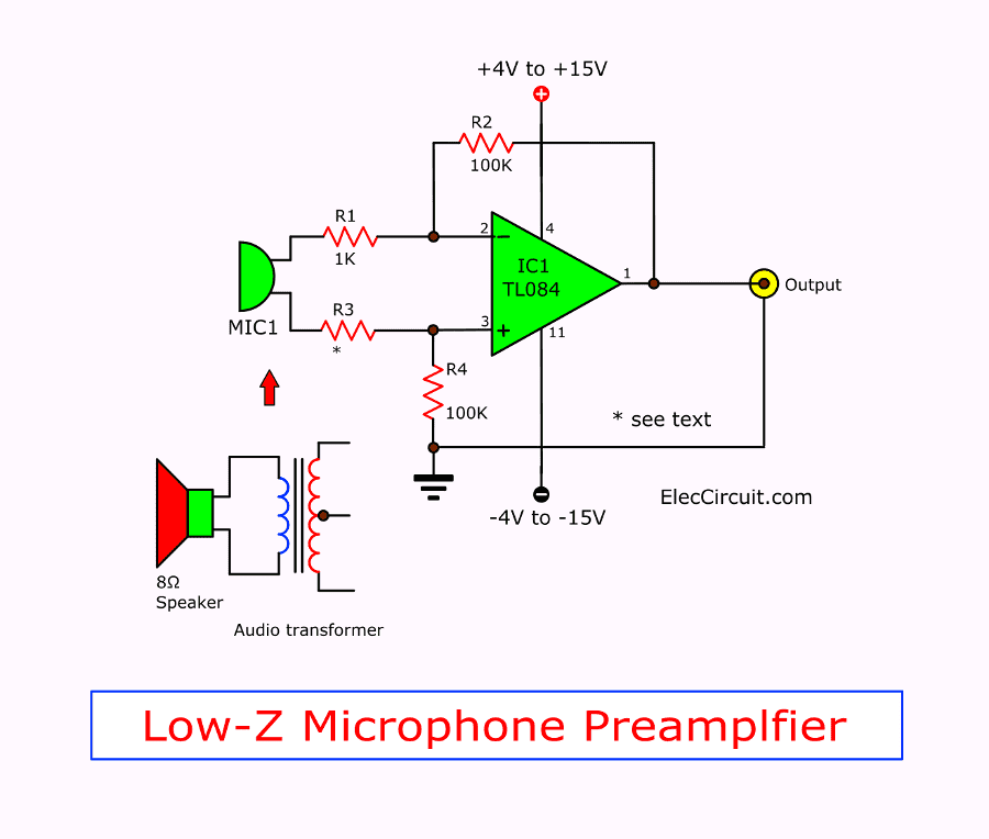
In contrast, we can use a small 8 ohms speaker as a microphone and need help from an audio transformer. It is matching to balance impedance.
Parts lists
IC1: TL084 JFET input OP-AMP
0.25W Resistors, tolerance 5%
R1, R3: 1K
R2, R4: 100K
SP1: 8 ohms speaker
T1: audio transformer
You may also like these:
- Simple Electronic Stethoscope circuits
- Simple Signal injector circuits using transistors
- 4 Electronic Siren circuits using transistors
- How to test a diode without meter
- Simple time Delay Circuit using MOSFET
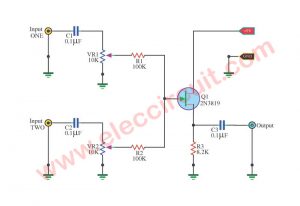
3. Infrared Voice Communicator using TL084
Do you want to play with Electronics?
We can apply these above circuits. To learn to send a voice via infrared light.
Look:
The infrared voice communicator circuit below.
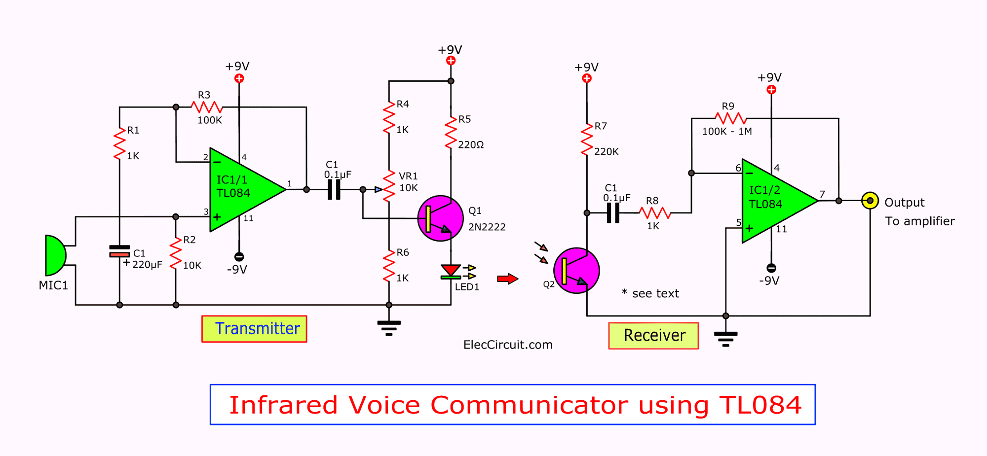
There is 2 section.
Transmitter: We use the Dynamicrophone preamplifier to get a voice to a signal. Then, use Q1-transistor to drive higher signal to the infrared LED. To transform the signal to infrared light.
We adjust VR1 to control a quality sound or a current to LED1.
Which R5 limits a max current no more than 40mA.
Receiver: The phototransistor will convert an infrared light signal to an audio signal. Then IC1/2 amplifies a signal to more higher. To go the input of power amplifier.
Recommend: 200 watt MOSFET amplifier circuit class G
Remember: We need to move LED1 and Q2 in a direction together.
Parts you will need
IC1: TL084C
0.25W Resistors, tolerance 5%
R1, R4, R6, R8: 1K
R2: 10K
R3: 100K
R5: 220 ohms
R7: 220K
R9: 100K to 1M
VR1: 10K Potentiometer
C1, C2: 0.1uF 100V Ceramic
Q1: 2N2222 NPN 0.8A 40V transistor
Q2: Phototransistor
LED1: Infrared LED

I love electronics. I have been learning about them through creating simple electronic circuits or small projects. And now I am also having my children do the same. Nevertheless, I hope you found the experiences we shared on this site useful and fulfilling.
mic to emplifire
in the article you state that the “gain=VR1/R1.”
but i think thats actually supposed to be “gain=1 + (VR1/R1).’
[typical gain equation for non-inverting op amp configurations]
pretty sure anyway, but seriously dont go placing any bets on my word on the matter. i like this site by the way.
Hello Junkaford H. McNuggetopoulis,
What you said is correct and I have corrected it. Thank you very much for your guidance. I hope you will visit our website again.
Thanks