This is an over and under voltage protection circuit device sound disappeared. when too much voltage 220V, and protection when pressure is too low with Using the relay cut off power when voltage problems. In particular, If the voltage of the motor is lower, the coils of it can be a burn.
Simple over and under-voltage protection circuit
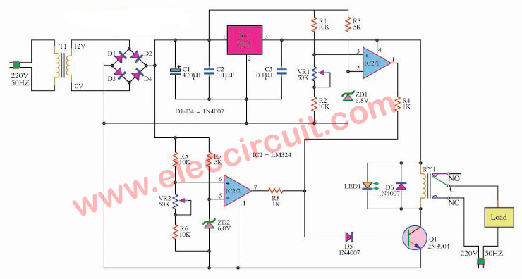
From the circuit when the voltage is 220 volts AC through a transformer T1. It serves to reduce the pressure remaining 12 volts, through a D1-D4 connected to Direct rectifier bridge circuit. To convert the voltage, alternating current to direct current. Then, through the C1 and C2 to the power filter smoothing. And entering a pin. Or input pin of IC1, a loan IC Rex bit computing to 12-volt power supply is fixed to the IC2. That it is IC Op Amp. Pressure acts edge IC2/1 High Voltage Detector, High Voltage ICs, if this current work to the Q1 and relay function, it works with. Thus cutting off power from the load instantly. The IC2/2 serves to detect the lower voltage. The two components can be specified by VR1, VR2. LED1 display when power or low power over a specified.
The parts list
- IC1: LM324_ Quad/ 1MHz/ Operational Amplifiers
- IC2: LM7812_______12V 1A DC voltage regulator
- Q1: 2N3904__45V 0.1A NPN Transistor
- D1-D4: 1N4007___1A 1000V Diode
- ZD1: 6V 0.5W Zener diode
- ZD2: 6.8V 0.5W Zener Diode C1: 470µF 25V Electrolytic Capacitors C2,C3: 0.1µF 63V Polyester Capacitor LED: as you like
How to build
This circuit is very useful. If you are interested in creating. It’s not too difficult. Because there is less equipment. And it certainly easy to buy. All equipment will be soldered onto the PCB purpose. Should be careful polarity of the diodes, Zener diodes, electrolytic capacitors types
Induction Motor Protection Circuit and working
This is a motor protection circuit. It will protect the AC motor burn out. Because of under voltage input. The principle is simple, it will check for voltage at all times. Normal voltage is 220V AC.
If the voltage falls below a preset. Relay will not work and the LED is a warning. Can be set to cut no-off in the voltage during the 168-227V.
As AC main in normal level, the relay will be connect to apply AC line to motor. And AC-line fall down lower than 10% of normal voltage the relay will cut off the load at once.
Until the voltage is restored to its original condition. So to get back into the circuit again. Ideally, block diagram in Figure 1.
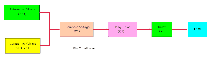
Figure 1 the block diagram
The working of the motor protection circuit
Figure 2 is a schematic of this project. There is an op-amp-IC1 as an input voltage comparator.
It will compare voltage between the reference voltage of ZD1- 3.6 volts the Zener diode , and input voltage from pin 3 of IC1 this voltage is divided by resistor-R4 and VR1.
We will set this voltage slightly lower than the reference voltage.
So this will apply a relay pulls in and connects AC electrical current to the motor or AC load.
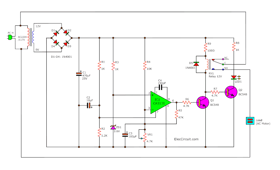
Figure 2 The schematic of Motor burn out and under-voltage protection
Pin 3 will be connected to capacitor C3 to reduce the fluctuating voltage to smooth. It may cause IC1, the relay-RY1 works with the error. This will not be good for this circuit.
We will also connect the resistor-R5 across pin 6 and pin 3 of IC1, to set circuit in Schmitt trigger form.
This is a special feature, it will cut off the load at once, when the AC main is under voltage into setting value.
If the main have ripple voltage,this will not works because the motor may be damaged.
Restarting with increasing AC voltage about 215 volts (as setting). So relay pulls in as Graph of time function in Figure 3.
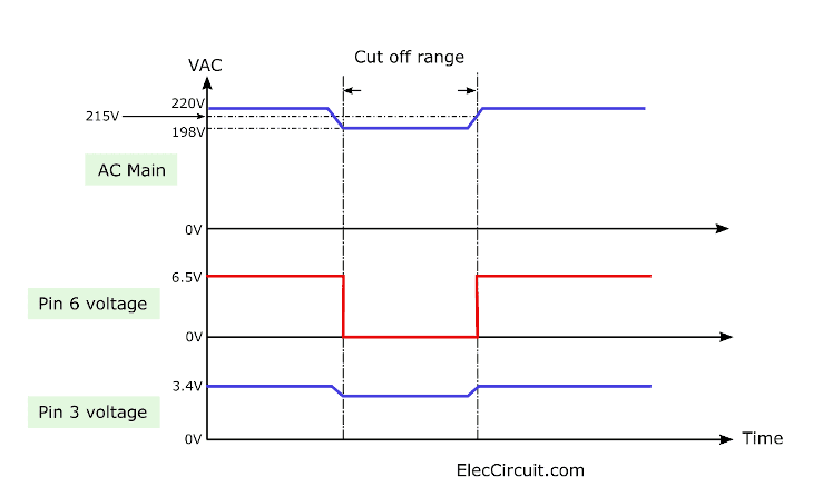
Figure 3
Reasons to Use IC1-CA3130 BecauseWhen conditions do not work, to make the output voltage is near 0 volts really. As a result transistor Q1 can not work absolutely.
But the common comparator ICs in not work state. The output voltage is 0.6 volts which may make the transistor can work.
The disadvantage of this IC is not able to tolerate the higher voltage of 16 volts. Thus in this circuit, we use voltage from the 15.8 volts power supply, then flow through the divider circuit of R1 and R2 cause have an 8.7 volts supply of IC1 only.
The transistor Q2 will drive LED to alert when under-voltage until electric devices cannot work.
But in normal Q1 will ON cause the voltage across Q2 is low so most current will flow to ground. Therefore, it is virtually no voltage to bias the Q2 As a result LED goes out.
Building
Before make the PCB as Figure 4 as copper PCB layout. Then soldering all parts on PCB as Figure 5, to begin with soldering low devices first.
For example resistors, diodes then put higher parts down until connecting a transformer and more parts. Do not hurry, especially for pins to make sure the correct position. Then wiring the different positions.
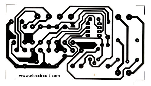
Figure 4 Actual size of single sided copper PCB layout.
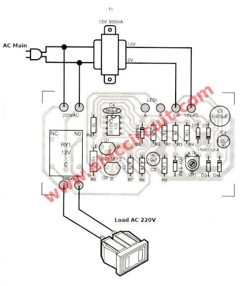
Figure 5 the components layout.
This motor protection circuit will be starting with input voltage AC 215 V. But the relay will fast cut off the load when the input falls to AC 198V by can adjust potentiometer -VR1.
Parts you will need
Resistors 0.25W +-5% R1, R3, R8: 1K R2: 1.2K R4: 10K R5: 47K R6, R7: 4.7K VR1: 4.7K Potentiometer Capacitors C1: 470uF 25V, Electrolytic C2: 10uF 16V, Ceramic C3: 100uF 16V, Electrolytic C4: 150pF 50V, Ceramic Semiconductors D1-D5___1N4001__1A 50V Diode ZD1_____3.6V/0.5W Zener Q1, Q2_____BC548___0.4A 40V NPN transistors IC1________CA3130___ Others RY1___Relay _____ 12V__1C T1___Transformer__12V/0.5A Box, PCB, Wires with plug 220V, etc.
Over and Under voltage protection of electrical appliances
This is an over and under voltage protection to all electrical appliances are safe. We use electronics circuits, high accurate work is fast LM393, AN6780 and more. Which cut off currents with power relay. I’ve presented this way, it is Over & Under Voltage protection circuit. But today, I’d recommend this because there is a very good following. 1. The relay will work all time in under or over voltage range. 2. This circuit will time delay all time when under or over voltage or power outage awhile. 3. Can use full performance, though under voltage to 12 volts or over voltage to 380 volts 4. Can be adapted to the circuit breaker when the power falls to 180 volts (or much – less). 5. Can be adapted to the circuit breaker when the power is too high from 240 volts or more (or much-less).
Over and under voltage protection circuit working
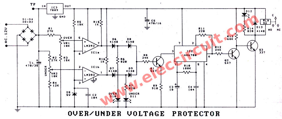
As Figure 1 is circuit diagram of this project. The voltage input is entered to a transformer that designed with primary of 380 volts and secondary of 20 volts. From transformer feature as above will cause can get voltage at secondary of 12 volts. When the input voltage is 220 volts as normally.
Over and under-voltage protection circuit diagram
And will be output voltage of 9.5 volts. When voltage drop down to 180 volts, this voltage as above will entered to diode rectifiers D1-D4. Notice: we use primary coil transformer is 380 volts to protect them Not damaged by too over voltage. The voltage that through a rectifier circuit will be separated to two way. First will be entered to IC3- LM7809 to The ability to maintain fixed voltage all time. Although the input voltage is lower as 110 volts or higher 380 volts to them. The circuit has excellent performance at all times. The other way voltage will be entered to R1, R2 and IC1 to compared with standard voltage from R5 and maintain fixed voltage to 5 volts stable by a zener diode-D5. VR1 will adjusted voltage lower than pin 6 just slightly,and will higher, when input voltage higher this setting voltage. The output voltage at pin 7 will be positive to enter through D6, D8 and R8 to base of Q1 cause Q1 working. While LED-D9 will grow to indicate we know that the circuit worked from the over voltage. The working of Q1 will makes pin 3 of IC2- AN6780 has electrical potential as the ground, cause output at pin 6 is positive, Q2 will work and reduce voltage at base of Q3 to lower until Q3 stop. The relay will break the circuit to protect the circuit that we use. When input voltage is normally high. The Q1’s base voltage will reduced until Q1 stop working. But IC2 will still continually works with time about for 3 minutes. Then relay so connects power to the normally electrical appliances. The VR2 will adjust the voltage at pin 2 higher slightly than pin 3. When input voltage lower than setting, when voltage at pin 2 lower than pin 3 will get positive voltage output pin 1 of IC1b fill through D7, D9 cause Q1 also work at over voltage. LED-D11 will indicate the under voltage. LED-D10 will indicate the over voltage.
AN6780-General Purpose Timer datasheet
The AN6780 and AN6780S are ICs designed for general purpose timer for long time. They consists of an oscillator, frequency divider (flip-flop 15steps), output circuit, and power circuit. A cycle can be freely set with the external resistor (R T ) and capacity (C T ) of the oscillator. Features • High inflow and outflow current : I O =±15mA max • Small variation of oscillations • Long interval timer setting : max 1 week
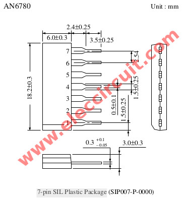
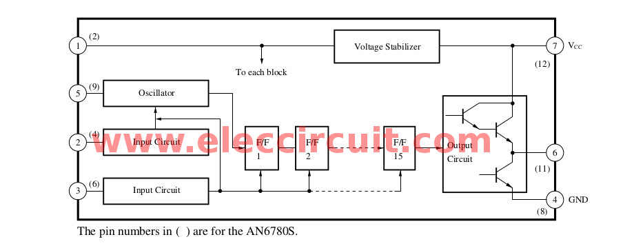
Figure 2 : Block Diagram Applications Timers, integrating timers, superlow frequency oscillators
Build over and under voltage protection circuit
As Figure 2 is the actual size of single-sided copper PCB layout. And assemble on PCB as Figure 3 completely. Then test the working of the circuit with applies a normal voltage to the circuit. The three LEDs will go out, next 3-5 minutes long LED D12 lights to show that the circuit functions normally.
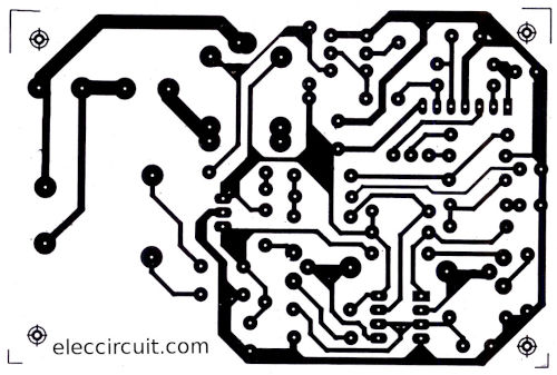
Figure 2 the PCB layout
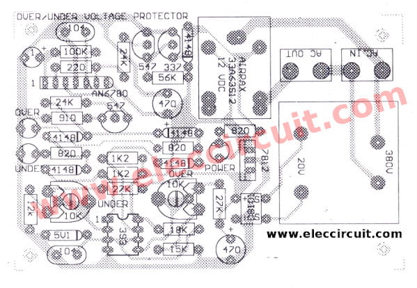
Figure 3 the component layout.
For LED D9, D11 if growing in this time, to adjust VR1, VR2 until both LEDs go out. Then test to reduce the voltage to 180 volts while adjusting VR2 until LED-D11 grow and within LED-D12 will go out. That show relay stops working and cut voltage of out the protected circuit show that it normally working. Next test add voltage rises up to 240 volts, then adjust VR1 until LED-D9 will grow while LED-D12 will go out, it indicated the relay stop and cut off voltage to also protect the circuit. If you do not have the AC variable voltage supply. You may use DC power supply adjustable voltage between 6-20 volts to connects at TP point. By the voltage of 13.5 volts will same input voltage of 180 volts and 17.8 volts for 240 volts
Components List
IC1: LM393 Low Offset Voltage Dual Comparators IC2: AN6780 General Purpose Long Interval Timers IC3: LM7809, 9V Fixed Regulator IC. Q1, Q2: BC547, 0.4A 40V NPN Transistor Q3: BC337, 0.8A 40V NPN Transistors D1-D4: 1N4007, 1A 1000V Diode D5: Zener 5V 0.5W D6, D7: Zener 3.9V 0.5W D8, D9, D13: 1N4148 D10, D11, D12: LED, as you want. The resistors 0.25W R1, R2: 27K R3, R5: 15K R4: 12K R6, R7, R14: 820 ohms R8, R12: 24K R9: 910 ohms R10: 180K R11: 220 ohms R13: 68K R15, R16: 1K The Capacitors C1: 470uF 35V Electrolytic C2, C4: 0.1uF 63V Polyester C3: 10uF 16V Electrolytic C5: 470uF 16V Electrolytic RY: 9V Relay 1 contact.
Related Posts


I love electronic circuit. I will collect a lot circuit electronic for teach my son and are useful for everyone.
some thing is wrong.the positive side of one of the z-diode should be in the non-inverting input. the other positive side of the z-diode to the inverting input of the other opamp, so to set the low and high cutoff.
kit pot seting.
What is wrong in the circuit schematic is the pin designation on IC2/2. Pin 6 is negative and pin 5 positive.
thnxs if you are
Sir I want to know the working of each component saperatly on the circuit. so please provide me the information as soon as possible.
why not consinder using lm 358 instead of lm 324?since 324 has four op amps and 358 has two
you use a lot of components. Why not use a window comparator with 1 reference zener diode and 2 pots.
Cracker is right. Helicoms is right.
Circuit is wrong.
Please be carefully.
sir i want explanation of the whole circuit please
sir can you please tell how to sets pot1 and pot 2? thank you.
how can you calculate variable resistor value ?
how we can analysis the above circuit
Thanks for every thing it is a perfect circuit
Circuit is gud. but I am confused that who will protect this circuit itself?! As transformer will burn due to over voltage.
Sir
I want to know about the designing of various components in the circuit..
sir ic1 pin 8 to 14 and ic2 pin 4,8,9,10,12,13,14. what is the fuction because they are not connected.
Hi dlaw,
Thanks for your feedback.
This circuit use 2 op-amp of 4 op-amp in IC-LM324.
Dear sir,
the above circuit you posted is very interesting to me. Really I’am very thankful to you for that.
But,can you please clarify me before i test the circuit.
In the given schematic diagram and in PCB layout D6,D7,D8,D9 are mentioned as 1n4148 zeners. and given in the parts list are D6,D7 = 3.9v 0.5w and D8,D9 = 1n4148 which one is correct…?
i got all the components from the market except AN6780 long interval timer. so, can u please tell me shall i connect Q1 547 collector directly to R12 24K resistance by removing five components IC2 , C3,C4,R10 and R11 ( Removing timer circuit)….? Thanks in advance…..:)
I have build the circuit with lm358.
It works the first time.
Thanks
This are tested ???????
Is it work???
please i saw a similar post in this link: freecircuitworks.blogspot.com/2016/03/low-battery-protection-and-alarm31.html which uses p mosfet or relay. i want members to check if i can also use that
please clrify regarding D6,D7 whether thes are Zenor or ordinary diod
where can i get the under and over voltage relays
input supply 550v output 550v
I read it and evaluate the circuit very carefully. I found this is really very interesting and attractive not only in term of home appliances protection but also the industry with little amendments. Only would interested to know how we can provide additional back emf’s protection. Because in case of low or high with relay tripping it might have produced the back EMF that may harm for the attached appliances.
Hope my comments would be useful for further evaluation, awaiting comments.
Regards/Kamran
Mob: 00966 500193412
Please, Can you assist us with the following:
To design a safety circuit that should provide for household
appliances for over-and undervoltage protection. The protective
circuit must immediately switch off upon detection of low-and
high-voltage household appliance and upon detection of normal voltage
switch on again after 3 minutes.
The protective circuit must comply with the following:
If the line voltage is within the normal range (100 to 130V ac), it
will wait for the protective circuit 3 minutes before the output will
be energized. During these 3 minutes there is an amber LED light.
If the line voltage is outside the normal voltage, the output of the
protective circuit will never be under tension.
If the line voltage is less than 100VAC, the protection circuit “low
voltage” must indicate by a red LED that lights up. If the line
voltage is present, the protection circuit must pass a voltage greater
than 105 Vac “normal tension” it will indicate by a green LED that
lights up.
Similarly, the line voltage protective circuit has to be higher than
130V ac “high voltage” will be indicated by a red LED that lights up.
Only when a voltage is less than 125VAC, it must indicate the
protection circuit “normal tension” by a green LED that lights up.
Upon detection of over-and under voltage protection, the circuit
should give a beep of 5 seconds. This should be constructed with an
opamp oscillator circuit in this functionality.
how can analysis the above circuit brife calculation each value
Hi,How to add time delay to this circuit with 324 C & D?Thank u.
Hai sir, may i ask if the D6 D7 are Zener diode or just a 4148 diode? the list of component says that it is a zener diode but in the circuit diagram it is a 4148 diode. Which is correct?
very nice . thanks
A hydraulic pump with a motor 15 HP, 480V, 3PH is powered by a combination starter with a 40A, 3P, 480V Allen-Bradley circuit breaker. Pump runs normally for a pressure at 300psi, and current 12A. When the pressure in a hydraulic tank reduced to very low level about 50 psi then the circuit breaker is tripped at a current 9A and the display screen showed “underload”. Could you please explain why the circuit breaker tripped at low current below overload circuit trip ? It happens again many times if the pressure would drop to very low levels.
Thank you
Dear Sir,
Please design a circuit board that should provide for AC220V power fluctuation protection. The protective circuit must immediately switch ON a 3 phase circuit breaker shunt coil (coil voltage is 220VAC) in the event of power fluctuation. Thank You
Hi, again
First, I am sorry. I cannot design a new circuit for you. Because I do not have free time.
But I want to help you a lot. Your job is important. This circuit idea may help you. Please understand here is just an idea for learning. It may be not good in real use.