This is a low pass filter subwoofer using IC 324 and some other components. which is mr Kunal Banerjee sent to me to publish on our site.It is very useful Thank you very much
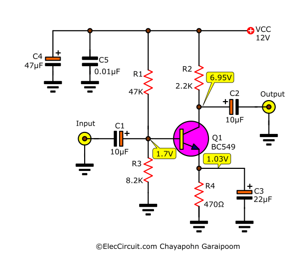
The Schematic
PCB LAYOUT ORIGINAL
The PCB layout original
PCB SILK ORIGINAL
The PCB Silk original
The components list
//Capacitor///////////////////////
————————————
C1=0.47UF/25V (Polarised Capacitor)
C2=0.47/63V (Polarised Capacitor)
C3=0.47UF/63V (Polarised Capacitor)
C4=47UF/25V (Polarised Capacitor)
C5=0.22UF/63V (Polarised Capacitor)
C6=2.2UF/50V (Polarised Capacitor)
C7=470UF/16V (Polarised Capacitor)
C8=104 ACE (Ceramic Capacitor)
C9=473 AEO (Ceramic Capacitor)
C10=104 ACE (Ceramic Capacitor)
C11=104J (Polyester Capacitor)
//Resistor///////////////////////
————————————
R1=100K
R2=6.8K
R3=6.8K
R4=6.8K
R5=47k
R6=47k
R7=6.8k
R8=470-OHM
R9=4.7k
R10=6.8k
R11=100k
R12=100k
R13=6.8k
R14=100K- “POT”
R15=100k
R16=6.8k
R17=100k
R18=4.7k
//IC and IC-Holder///////////////////////
————————————
IC1=”LM324″
IC1 HOLDER=14 PIN ‘DIP’
Related Posts
I love electronic circuit. I will collect a lot circuit electronic for teach my son and are useful for everyone.
need really quick help with the connection of the ic??
hi new BT
hi… nice to this post and many thanks,
i need a guide how to add volume control? i’m glad to get your answer to my email [email protected]