How to use TL497 as the switched-mode power supply schematic that outputs a current of 500mA, and there are 3 models: step down, step-up, and inverting voltage converters. Now, a switching power supply is highly popular. We are used to suggesting a lot of projects.
Those who want the switched-mode power supplies that have small size and high efficiency. We think that this article is what you want, but tell before that they can provide a lower current of about under 500 mA.
So Suitable for the study only. But can seriously apply, and can be easily increased current to widely applied.
We intend to show the third model. See below!
- Step-down voltage circuit: can reduce the voltage from the input of DC12V into the output of +5V.
- Step-up voltage circuit: can increase a voltage level from the input of DC 5V to DC12V at the output. And Finally,
- Inverting switching voltage regulator circuit: from a positive voltage DC 5V to a negative -5V at the output.
What is a switching power supply, and how does it work?
The basic principle of the TL497
This Generation is extensively ICs. A TL497 of Texas is very good switching regulators IC,it is popular over than 40 year old. Now also still use so well. We see the internal structures do in Figure 1.
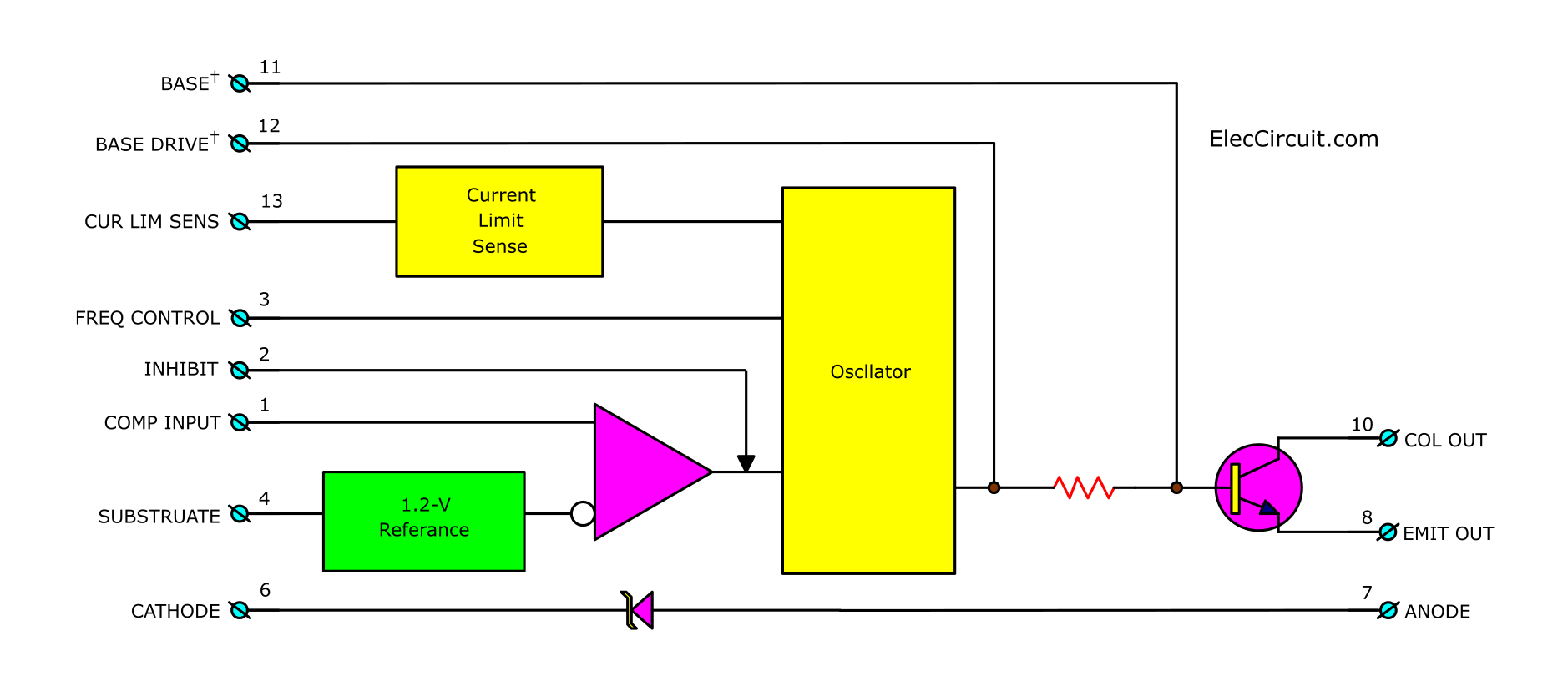
Internal structures of TL497
Note: This project also use TL497: Make solar aa battery charger by TL497
The diode is inside but should use be careful
We will see that at pin 6 and pin 7 has one rectifier diode. But do not glad that It is free diodes, because The manufacturer does not recommend using it on inverter mode or inverting voltage circuits since has a voltage across it too much. Which will result in the work of the external transistor that is connected with together errors.
Thus in this work so should use the external diode better.
The reference voltage of 1.2V
Inside this IC also has A reference voltage of 1.2 volts. Which Manufacturer guarantees that this reference voltage of 1.2 volts extremely. If the error is less than 1.08 volts and not higher than 1.32 volts. Which we can not measure this voltage. Because no external connections.
This reference voltage is connected to a positive input pin of internal OP-AMP, which serves to Amplify error, next the negative input is connected to outside IC, to connects with the network for is negative feedback.
Checking the amount of current
Then, is a current checker that serves to check any current at the IC itself. And next, to control the amount of current in the range determined. Which can be obtained current up to 500 mA. But we can limit this current by changes resistance across pin 13 and pin 14, which we can find this resistance from 0.5 divided by the maximum current as want.
Read also: How to use 7805 voltage regulator
The inside oscillator
The inside oscillator Normally will provide an output voltage that has a constant amplitude, The average voltage change due to the change in the frequency of these oscillators. The output is connected to the base of the inside transistor. Which of the pin base, emitter, and collector are connected to outside, making can easily work on three-mode.
The errors extensions
The error extensions will work, when we enter the voltage to the input way, now no voltage at the output. The section is the error extensions. Which normal will be connected to the output of all circuits, not get any voltage. So, it will send a signal to control the oscillator to generate frequencies, that has the provide voltage range over than stop range.
Now, there are voltage appears at the output, then The errors extensions will also get voltage, and next it will control the output voltage, as the value of network determines at the output there.
In this time, we know the internal structure of the TL497 enough. Cause understand the principles working roughly, then Let’s view application on three projects below:
1. Step down voltage circuit
See a circuit name, Do not think that just put a resistor serial only. Because, if you use a resistor to reduce the voltage, the output is constant voltage particularly the current one size only. If current decrease or increase. the voltage will also change. If using these switching controls, it will be a constant voltage for every current size.
Figure 2 is the step-down switching voltage regulator circuit that serves as reduce level voltage circuit. Both C1 and C2 filter the voltage to smooth up before sending to IC1, R1 are determined the size of the maximum current that limits the current at 500mA.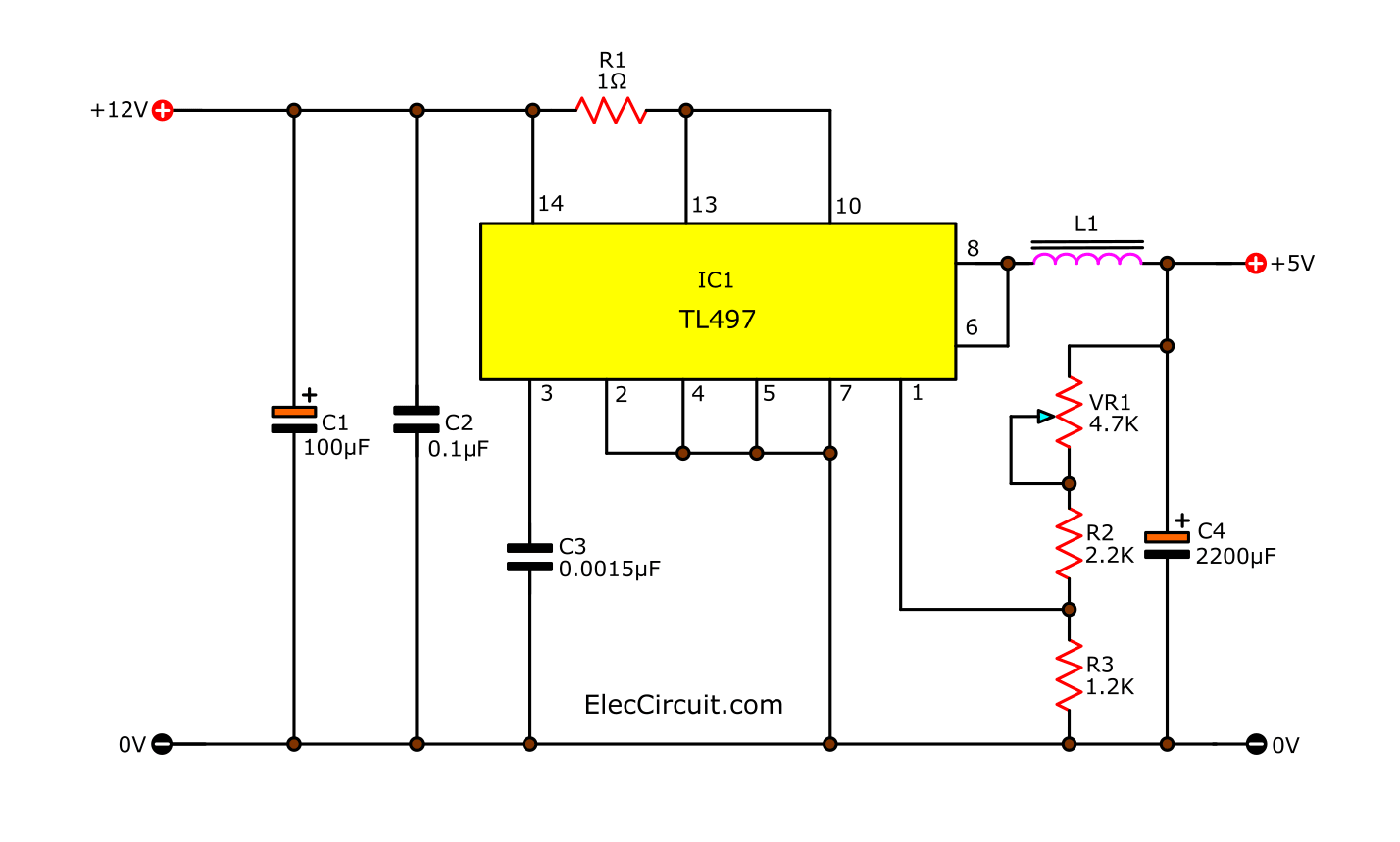
Figure 2 is the step down switching voltage regulator circuit
This performance of the circuit is Certainly under 100%, so the input current of 500 mA will into maximum current output of about 400 mA only.
From the experiment measure, the input current equals 115 mA at input voltage 12V. While the output voltage of 5 volts. and the current 200 mA. When thinking as input power equals 1.38 watts. then the output power equals 1 watt. And there is an efficiency of up to 72.5%. (Not believe, press the calculator). While the common series voltage controller circuit has an efficiency of 40 % only.
Come to see the circuit again, the output from IC1 at pin 8 is connected into the current filter circuit include L1 and C4. The C3-capacitor is determined a period of frequencies from the oscillator within IC. Which it set particular a pulse range as “1” only. The next width of pulse range “0” is determined by external power consumption.
VR1, R2, and R3 are the negative feedback network, by bringing a signal come from the output voltage. The setting R3-resistor has a value is 1.2K. Which this value is set to easily Calculation. Because the voltage across this R3 must be equal to 1.2 volts. While the output voltage is equal to that want.
Reason must equal 1.2V because must enter this voltage to the input of the errors extensions. When the voltage is lower than 1.2 volts. (Internal voltage reference IC.) It means that the output voltage is pressed down. At the errors extensions circuit will send output to control a creating pulse of oscillator section that range is “0” shortened. To voltage higher average and much than pulling the current of the load.
The output voltage can adjust by VR1. Which will be the result, the voltage drop across R3 changed. Making oscillator generate the frequencies also changed. Finally, the output voltage changed by adjustable from 3.4V to 8.1V (can set voltage of : 4.5V, 6V, 7.5V) As the value of devices defined in this Figure 2.
While in use, If there are pulse broke free. This may generate a frequency of oscillator and capacitance as the current filter at the output do not match together. We modify with one capacitor of 0.01uF across to output will better.
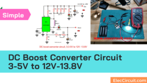
2. Step-up voltage circuit
This circuit is called other name that dc boost converter circuit as shown in circuit below. Which most working like the step down switching voltage regulator circuit, Except for the output that will cause get higher voltage than input, that can change from 5.9 to 15.9 volts.
Although this circuit will provide the output voltage higher up, but the current will lower. Thus, the current input will must much than output. And if input has maximum current, but will send current 208mA only. This is the limited current between 170mA to 180mA.
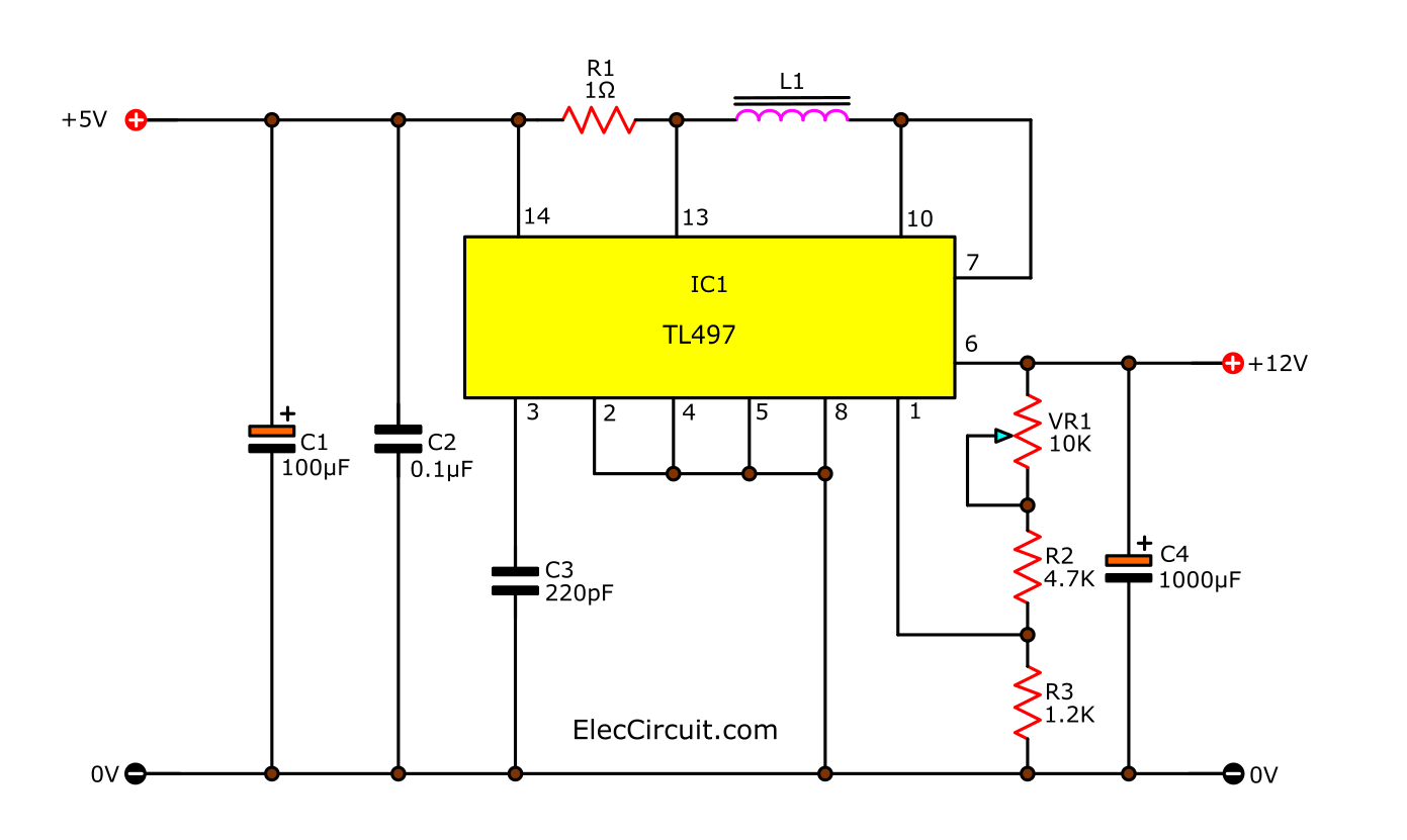
Figure 3 the step-up switching voltage regulator circuit or dc booster converters.
The output of circuit has additional voltage because the properties of the inductor L1 that connected in series at pin 13 and pin 10.
3. Inverting switching voltage regulator circuit
In Figure 4 Overall functionality remains the same as 2 model, ago. But different at output because this circuit provide the output voltage with alternating polarity input. Notice pin 4 which is substrate normally will connected to ground that is negative. But this event of circuit, need to have the ground at output that is positive. Thus so must take this pin to output.
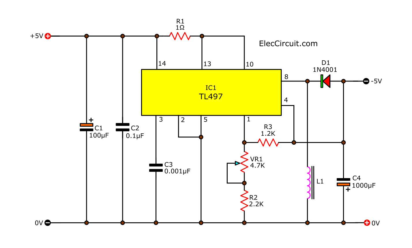
Inverting switching voltage regulator circuit
Which will make the voltage at pin 1, when compared with substrate still is +1.2 volts as previously, Will be seen that the R3-resistor is connected, switch with 2 circuits ago. To get the same output voltage monitoring.
The section that is the negative voltage consist of L1 and D1. The pulse from IC1 will be induced at L1. Based on file properties of the inductor. Cause negative voltage up. And the positive voltage range will be Blocked by D1 is off to the outside.
How to build these projects
All devices in the 3rd circuits. You can buy them at electronics stores online. and then Can make a PCB and put all components as layout in Firgute 5.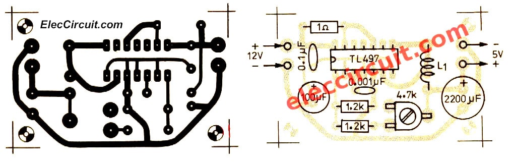
Figure 5 The single-sided PCB and the Component layout for the Step down voltage
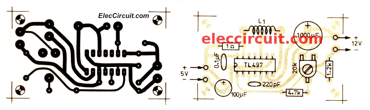
Figure 6 the-single-sided-pcb-and-the-component-layout-for-dc-boost-converter-projects
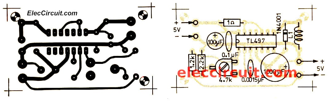
Figure 7 the-single-sided-pcb-and-the-component-layout-for-inverting-switching-voltage-regulator-projects
The components list
Step down voltage circuit
C1: 100uF 16V, Electrolytic Capacitors
C2: 0.1uF 50V, Polyester Capacitor
C3: 0.0015uF 50V, Polyester Capacitor
C4: 2200uF 16V, Electrolytic Capacitors
IC1: TL497, 500-mA Peak Step-Up, Step-Down, Inverting Switching Voltage Regulator
L1: 60 uH Inductance
R1: 1ohm ¼ W + 5% Resistors
R2: 2.2K ¼ W + 5% Resistors
R3: 1.2K ¼ W + 5% Resistors
VR1: 5K potentiometer
Step-up voltage circuit
Capacitors
C1: 100uF 10V, Electrolytic
C2: 0.1uF 50V, Polyester
C3: 220pF 50V, Polyester
C4: 100uF 16V, Electrolytic
IC1: TL497
L1: 40 uH Inductance
R1: 1 ohm ¼ W + 5%—Resistors
R2: 4.7K ¼ W + 5%—Resistors
R3: 1.2K ¼ W + 5%—Resistors
VR1: 5K potentiometer
Inverting switching voltage regulator circuit
C1: 100uF 16V— Electrolytic Capacitors
C2: 0.1uF 50V—Polyester Capacitor
C3: 0.001uF 50V—Polyester Capacitor
C4: 100uF 16V— Electrolytic Capacitors
D1: 1N4001—50V 1A Diodes
IC1: TL497- 500-mA Peak Step-Up, Step-Down, Inverting Switching Voltage Regulator
L1: 25 uH Inductance
R1: 1 ohm ¼ W + 5%
R2: 2.2K ¼ W + 5%
R3: 1.2K ¼ W + 5%
VR1: 5K potentiometer
Not only that You can look other power supplies: Learn more
Related Posts
I love electronic circuit. I will collect a lot circuit electronic for teach my son and are useful for everyone.
pls. help m,TL496 ic is available,what ic can i replace for my mini inverter project to do?
Hi, Mel Emberga
Thanks for your feedback.
I don’t know it can replace them.
I am sorry.
smps material very useful to us
i love too electronic circuits
Hello Budi m
Thanks for your feedback. Me too!
Have a good day.