This is a NiMH battery charger circuit with auto cutoff. A nickel-metal hydride battery, also known as NiMH, is a secondary cell. It is a type of rechargeable battery. They are used extensively, in cameras and other electronic devices.
Because it is cheap and very common for AA cells in many capacities as required. We can replace the generic battery right away.
Important. We can a new recharging a lot of times depends on its capacity.
- Lower capacity, 1700 up to 2000mAh can be recharged up to 1000 times
- 2100 to 2400 mAh batteries can give between 600 to 800 times
- The greater power capacity, AA 2500 mAh rechargeable batteries can only be recharged approx 500 times
All rate in slow charge mode.
We will see that it saves a lot of money. But it needs a good battery charger. We can buy an instant one in a store near your house.
But we are electronics inventors. We should build it ourselves. Because it is cheap and of good quality.
Feature
The project is the NiMH battery charger circuit with automatic cutoff when fully charged. You can charge the batteries from 2-8 pcs, depending on an input voltage.
In the circuit has two LED indicators.
- First LED, show charging status, when the battery is full, it will be off.
- Second LED, connect the battery correctly.
The input voltage can use the power supply of 12V, 2A. At the charged current up to 800mA.
Note: This circuit is also an automatic NiCd battery charger circuit, too. For example Nicad battery 1500mAh, 1.2V. Now I never see under 500mAh.
How it works
Updated: 22 Jul 2019
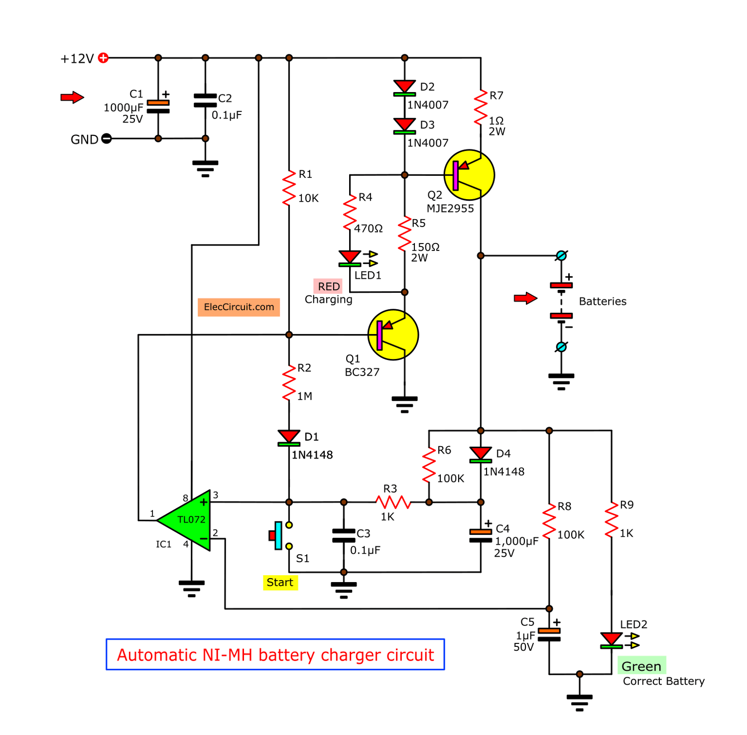
Figure 1 Automatic NiMH battery charger circuit using TL072
The circuit in Figure 1, when we connect a battery to both points P3 and P4. LED2 will glow up, in case all battery connects correctly. If the battery reverse polarity, this LED2 goes out, we need to check them again.
Some voltage from the battery is compared to IC1. Which the TL072 is set in a voltage comparator circuit at between pin 2 and pin 3.
In case the voltage from the battery to charging each cell is still low. The output from pin 1 of IC1 will send to a transistor Q1.
The transistor-Q1 will switch on-off a working to transistor-Q2. So the current can flow to the battery.
While the circuit is charging, LED1 will show charging status.
When the battery is full, its the voltage is compared at the IC1 will make an output at pin 1 of IC1 go to stop working of Q1. Then also causes the Q2-transistor stop.
You may also like these:
The end of battery charging and LED1 is off, to display that the battery is full enough.
The amount of current in the charging battery of the project is determined at 800mA. By there is R7-resistor is a current limiter as above.
The S1-switch, to start charging, in the case that the battery correctly. We also press S1 to recharge again, to test that battery is fully or not.
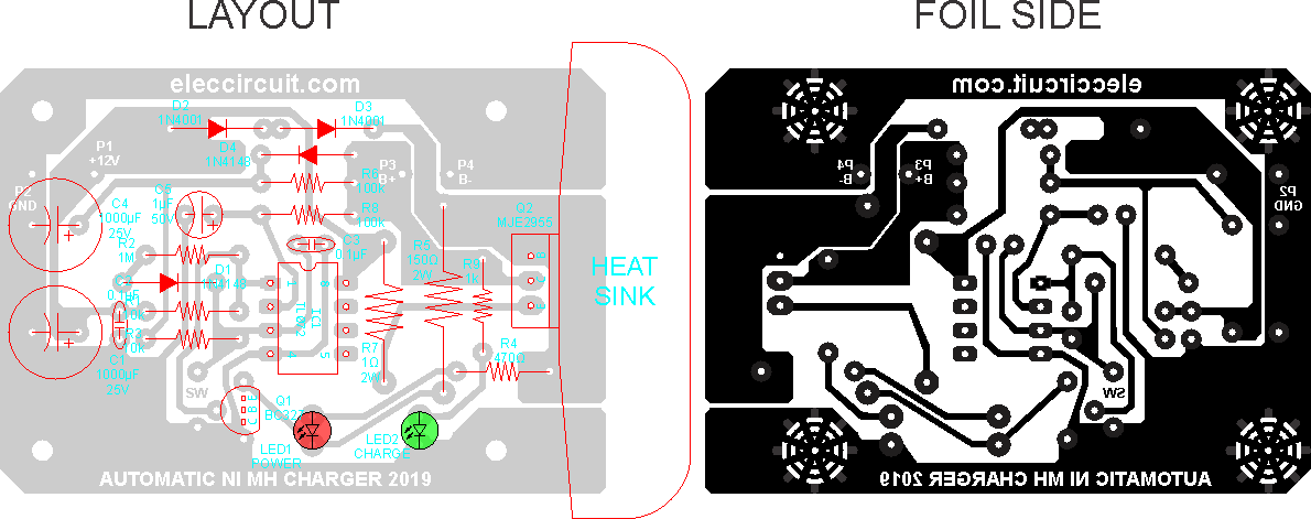
Here is PCB layout by Lennie Zink. Thanks for your share and suggestions.
He is an excellent electronics hobbyist. I like his life. Read more: Lennie’s Projects
How to builds this project
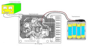
This project has a few components so easy to build. First, make the single-sided PCB layout as Figure 2 or can also use easily the Universal PCB Board. Then assemble all parts on the PCB as Figure 3 We just recommend a short detail, because I think you can create easily yourself.
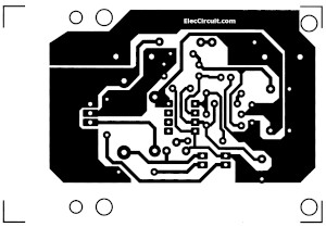
PCB layout of Automatic NiMH battery charger circuit
The Component layout for the PCB.
The Detail Components
IC1 = TL072—LOW NOISE J-FET DUAL OPERATIONAL AMPLIFIERS = 1 pcs.
Q1 = BC327—50V 800mA PNP Transistor = 1 pcs.
Q2 = MJE2955—50V 3A PNP Transistor = 1 pcs
D1,D4 = 1N4148—75V 150mA Diodes = 2 pcs.
D2,D3 = 1N4001—50V 1A Diodes = 2 pcs.
Electrolytic capacitors
C1,C4 = 1000uF 25V—Electrolytic capacitors = 2 pcs.
C5 = 1uF 50V—Electrolytic capacitors = 1 pcs.
C2,C3 = 0.1uF 100V—Polyester capacitors = 2 pcs.
0.25W 1% Resistors
R1 = 10K = 1 pcs.
R2 = 1M = 1 pcs.
R3,R9 = 1K = 1 pcs.
R4 = 470 ohms = 1 pcs.
R5 = 150 ohms—2 watts = 1 pcs.
R6, R8 = 100K = 2 pcs.
R7 = 1 ohms-2 watts = 1 pcs.
Also these NiMH battery charger circuit
GET UPDATE VIA EMAIL
I always try to make Electronics Learning Easy.

I love electronics. I have been learning about them through creating simple electronic circuits or small projects. And now I am also having my children do the same. Nevertheless, I hope you found the experiences we shared on this site useful and fulfilling.

Hi, it possible to put USB at P1 and can I replace IC1-TL072 to IC LM317.. plus can I add solar panel to this circuit?
No you cannot use USB port. Voltage only 5V.
LM317 is a regulator – TL072 is an Opamp. Two different components altogether, so you cannot do this. Yes you can put a 12V solar panel on input.
Regards,
Fred
what is the range of battery to be charged
Is it for 9v battery? If not than what corrections I should do in it to make it work fpr 9v rechargable battery?
hi, may i know what kind of switch was u used? is’t relay ? and can this circuit charging 9v of battery ? tq =)
can I place only one cell of 1.2 volt 2800mAh for charging/ any changes in ckt for same automatic working?
for more then one cell charging, connection parallel or series of cells?
thanks in advance 🙂
Hello,
Thanks for the circuit!
I need to charge a pack with 7x 1.2V NiMH batteries (8.4v totally) and it’s a soldered package, so I cannot charge each cell individually.
Is this charger able to charge this battery package?
Thank you,
Rodrigo Wantuk
Hello,
Thanks,
I need to charge a pack with 4x 1.2V NiMH batteries (4.8v seried package).
Is this charger able to charge this battery package?
thanks.
s.a.miryaghoubi
Hi s.a.miryaghoubi,
Yes, you can use it.
hi
¿I can increase the input voltage to charge 15 cells in series?
I like the circuit and could have a use for it. My question is how many cells can be charged at on time? I have a 6 cell pak that I need to charge. All cells are in series and cannot be separated. Thanks much for the help.
Hi KI4DKX,
Thanks for your feedback.
Yes, you can buy you must change the level of parts. And more.
Which I cannot tell you more details.
what battery voltage is this for ?
battery with 3.6V or two AA 1.2 + 1.2 ;thank you.
Great circuit; however, I am confused about how to use the charger correctly – please clarify the statement below from the above project description.
“The project is the Ni-MH battery charger on automatically shut off when fully charged. Can charge the batteries from 1-10 pcs. Depending on the input voltage.”
Does this statement mean that a variable power supply must be used?
If the above statement is true then, the variable power supply output voltage should be adjusted between 12-16V to be able charge Ni-MH battery packs with a voltage range of 1.2 (1 AA battery) to 12V (10 AA batteries). Correct?
Thank you for clarifying how to use this project correctly.
Circuit subject – Automatic ni-mh battery charger can make by yourself —
After more research I determined that a variable power supply that can provide a range of voltages from ~3.15V to 18V is needed.
This range was determined by adding ~1.65V (voltage needed to charge 1 AA NiMH battery)to the ~1.5V needed to operate the charger circuit, which is ~3.5V then multiplying 3.5V by the range of cells that may be charged (1-10 cells).
With this in mind I have decide to build a variable power supply based on the LM317. Then put both circuits in one project box with a selector switch and presto – a combo variable power supply and NiMh battery charger.
Cheers
Hello i build this circuit.At the moment it works in the part the the green led glows when i connect 1 battery.I input 12v as you clarify .The charge starts when i press button,red light glows and in my multimetr shows 880ma of current that flow in the battery.My problem is that charge does not stop .Battery is burning hot and still red led does not go off still charges.I am assuming that if i let it go it will explode.I tried with 2 batteries in series some effect what could be wrong please?should i lower the input voltage ?The reason i built this charger is for charging 6 cells of1.2 in series.Will this work without mod?
I think the batteries must be in parallel situation . not series .
Thank you Trm090 for verifying what I suspected. Whatever small currents exist going towards ic1 + terminal make sure that v+ is always lower than v- (which tracks the battery itself) and ic1 output is always low and thus forcing charging to continue.
Some means of letting v+ actually exceed v-, as battery gets fully charged, is required.
plz help me to design the pcb…guide me how design it on pcb
I built this circuit. It will charge a 9v battery very quickly. However, it will not automatically shut off. It will overcharge your battery if you leave it connected too long. v+ voltage never even gets close to v-.
I choose this circuit design as my mini project but I was ask to provide the design that the calculations for the selection of each component pls I need your help or any body that can contribute.
thanks for your concern.
hello sorry for my english i’m portuguese.
i built your circuit it is work but when i connect power 12v led red glows on without press button led green works fine.
can you help me??
thanks
hernani coelho
I think R6 must be replaced with on 70k resistor in series with one 100k trimer, so you can ajust the point you want to stop charging the battery
Hi,
I have created a customized 12V 10AH NiMH battery pack. Single battery is of 1.2V & 2A. So I have arranged 10 batteries serially and 4 parallel. So I need to charge single battery pack having total 14 batteries. Can I recharge them using your battery charger?
I don’t see how this circuit can work to stop the charging process and a number of people have said that it doesn’t stop charging and ther battery gets very hot. The two inputs to the TL-072 chip are effectively connected to the same point at battery contact P3. The voltage rise will be slow and gives plenty of time for the 1000uF capacitor to charge and any leakage current will make matters worse. Circuit Guy said in October 2015 that it needs some extra components to allow V+ to become greater than v- as the battery reaches full charge.
hi .this circuit is really helpful . but I cant calculate and analysis it .please help me .its for my mini project
thank you
Hi, maybe a stupid question, but I’m still new to this matter – could this circuit work for lead acid based batteries, and in particular 6V 4.5AH? If not could it be modified somehow for this purpose?
mje 2955 cant find with right pins
Hi kanwer
Yes, Pin of MJE2955 not correct.
It must be B-C-E.
Thanks for your feedback.
I tried everything possible but this circuit doesn’t work
It doesn’t turn on mje2955
Hi Mickybuttar,
Thanks for the good questions.
I’m sorry to hear that. This project should work well, please wait for me.
My son will preview the project that works.
Now I do not want you discouraged.
Please check it again.
the mje2955 is getting heated up as well as the 1 ohm resistor. my battery got overcharged and exploded. i connected 2 -2700mah ,1.2 v battery in series. also the charging is automatically switching off even if the battery is not charged. it is getting off every 15 min. the supply given is 12v regulated via 7812 and transformer used is of 12 v,1 amp. what should i do to solve the problem.
Please use 10 1.2v batteries to make it 12v. This project is for 12 battery pack I believe
Can I charge single 1.2V battery with this circuit?
Hello Hamaza,
Yes, You can do it.
There is LED2 will glow In the event of connecting correctly of all battery. Can we change the LED 2 by short circuit after the making sure the connection is correct because if we let it glow all time it might discharge the battery in few amounts.
Pin 2 of IC 1 should be connected to a fixed reference and not on the same node as pin 3 in order stop charging when the battery voltage rises to a desired level.
I think the batteries must be in parallel situation . not series .
the IC is getting way way too hot? why?
Hello Marco,
I am so sorry to hear that. Please check again. Something is wrong. I bought this kit. It runs well, fast charge with high current.
Just completed this circuit (during stay at home for virus isolation) and I cannot get it to work. It seems the IC1voltage comparator is not working as the inverting and non inverting inputs are both sensing the same voltage (ie battery). The transistors conduct when S1 is pressed, pulling Pin 3 to 0 volts, there by reducing the O/P on pin 1. Am I missing something? Any help would be appreciated. Thanks.
You should courses for writing good English
your English is complete nonsense
Hello Adam,
Thank you very much. It is true.
Will it be possible? In my English, I get better. I am 47 years old, my brain is quite slow. Please suggest a simple way to communicate clearly is enough.