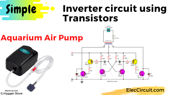
This is a simple inverter circuit on 30 watts, It converts DC voltage from a 12V battery to AC 220V-230V at 50Hz which is electricity the same use in your house. It can provide 2-3 Air pump or other. You will like them because so cheap and easy to builds. And Below there is a 2N3055 inverter for higher power than this.
The Air Pump requirement
Before see the Aquarium Air Pumps are chosen as Figure 1, He said that small, cheap, and works great.
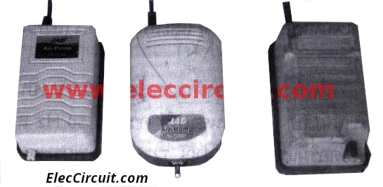
Figure 1 Aquarium Air Pump is chosen
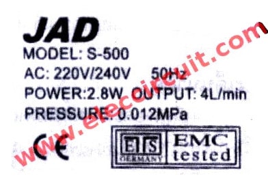
Figure 2 The Aquarium Air Pump special feature.
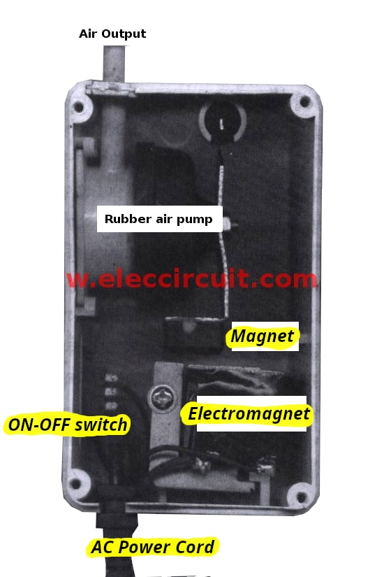
Figure 3 The internal structure of the aquarium air pump.
Then, what is required? When looking at its bottom will see that a special feature as Figure 2 notice Importance: Use for voltage of 220 volts, Frequency of 50Hz(AC:220V/240V 50Hz) And use AC electrical power of 2.8 watts (power:2.8W)
Recommended: Learn transistor works here
The internal structure of the Aquarium Air Pump.
The air pump consists of a rubber ball (similar to a pneumatic for bicycle tire) to generated to output. By The driving force between the magnet and electromagnet.
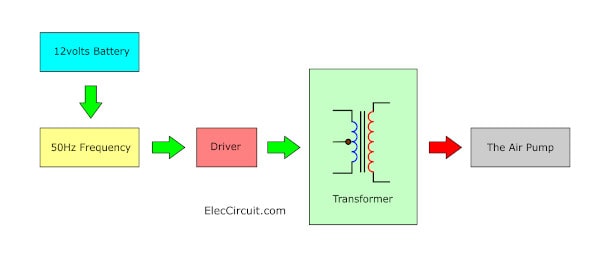
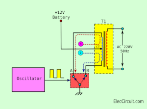
Block diagram of the 12-volts battery to 220V AC 50Hz circuit.
Then, try to apply AC 220V to them will see that Permanent magnet vibrates very fast, so Pumping the air out. Near the same that have a similar device is a transformer coil pack, but with only a single coil. It is the electromagnet there.
The AC electricity cause Electromagnetic field collapse the alternates a pole continually, Magnetic oscillate shorter, Set rubber air pump is working.
Issues to think
In the detail of the Air pump above, We can handle issues, as follows :
1.The 50Hz frequency: has very important, if too low-frequency Strong winds are not very and when high frequency the coil will respond before until stationary to do.
2.The Waveform balance is best perfect, When see in home electricity waveform will see that has peaked to peaks high-low. Which we can use other waveforms instead so may use the square wave.
To design power converter circuit
As above, we have to convert the 12V battery to 220V AC 50Hz. by an inverter circuit. Which we can draw the simple block diagram As Figure 4. When applying a 12-volts battery to the 50Hz frequency generator on the square waveform.
After that, the current will flow through the amplifier up. To drive the primary coil of the transformer and Inductor current to the secondary coil. into the 220V AC 50 Hz as you need ready to use with the air pump.
The frequency generator circuit
In conditions, I select the oscillated generator circuit by dual transistors. As used an 2 led alternating flasher circuit. Figure 5 is the 2 led alternating flasher circuit.
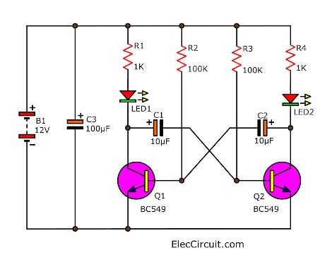
Figure 5 is the 2 led alternating flasher circuit using two transistors.
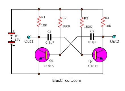
I modified to change some devices until will be the 50Hz frequency generator circuit as Figure 6
Figure 6 the 50Hz frequency generator circuit
The selects the parts
1.Q1, Q2 I selected the transistors as a number: 2SC1815. Because cheap, suitable for use not over than 20-volts and 0.1A, normally gain under 200 times.
2. R1, R4 are resistors same load of Q1, Q2. When we want to set the waveform is balance (50% duty cycle) both have voltage or no voltage.
In this case I select both R1,R2 = 10K will can cause current flow to lead C-E of Q1,Q2
called “ICQ” by ICQ = (VB – VBE) / R1_______(1)
To set : VB = 12V (battery voltage), VCE = 0.3V (voltage across pin C-E while full conduct current)
R1 = R2 = 10K
Put in
ICQ = (12V – 0.2V) / 10K
= 1.18mA
3. R2, R3 are resistors to bias at B of Q1, Q2, they so conduct current. By resistance of R2, R3 has an effect on frequency and waveform so should set equal.
By R2 value : (Vb – Vbe)/ Ib
We can set them : VB= 12V, VBE = 0.6V(voltage across BE pin)
But now we not know IB? so do below:
IB = ICQ / hFE
We dertermaned value by ICQ = 1.18 mA, hFE = 20 times.
IB = 1.18 mA / 20
= 0.06 mA
Therefore, we insert them into (1)
R2 = (12V – 0.6V) / 0.06mA
= 190K
But this value not sell in any store, so use 180K instead better.
4. C1,C2 are capacitors that set frequency output, should same value, so calculate only C1 in single. In this case, I choose a 0.1uF because is medium , easy to find.
from: T = 0.7 x R2 x C1
Back new recipes (with move sideways) is
C1 = T/(0.7 x R2) ___________(A)
Try to configure R2 = 180K; But T is unknown, Is looking:
By T is time period associated with the frequencies (F) is:
T = 1/F
Substitute:
T = 1/ 50Hz = 0.02S
Try substituting values in: (A)
C1 = 0.02 S /(0.7 x 180K)
= 0.15uF
But I used 0.1uF because nearby can be used interchangeably.
Increase current to drive transformer
Next, the current amplifier circuit by increasing the signal from the frequency generator rises up before driving the transformer next, this is the important section.
First of all, I think to use 2SD313-transistor only one. Because Can tolerate a high current of about 1A. ( at 12V). But has disadvantages are low gain to have add increase current transistor another one.

So is the simple current amplifier circuit as Figure 7. When is set as this Darlington form, causes very high gain and has high input impedance, so reduces noise so much.
Figure 7 The 30 watts simple inverter version 1
Because we need waveform that has high power both positive and negative. So should use transformer that has center trap and use two amplifier set, that has same electricity feature.
By Each set is alternately working, when Q1 conduct current, result to Q2 not works. So current flow through R4, R6 provide current bias to Q4, Q6 conducts current. Result have current from the battery to transformer coil.
But when Q1 stop cause Q2 works so has current flow through to R1,R5, to provide current trigger to Q3,Q5 conduct current replace Q4,Q6. Thus current from battery so flow through other transformer coil instead. Cause electricity inductance through the transformer switch between positive and negative with high power.
Selecting parts for drive transformer.
1. Q3,Q4 are pre driver amplifier, use many number that is NPN type, I choose 2SC1815 again.
2.Q5,Q6 are high output drive amplifier transistors. I selected a 2SD313 because high current collector more than 1A and cheap. You can use H1061 or TIP41 quality better (high current and voltage)
3. R5,R6 are resistors to provide current to bias the base of Q3,Q5 and Q4,Q6, which they will work alternately as principle above. In this case I so choose them are 4.7K.
4. T1 is transformer increase voltage from 12VAC into 220VAC at frequencies of 50Hz.
First we have to know power to use before. Which is 8.4W as the air pump spec. I set up to 10 watts better. And then power output is 10 watts.
Therefore, power input of the transformer is also 10 watts when use 12-volts battery will use current is : 10W/12V = 0.83A or about 1A.
Real application circuit
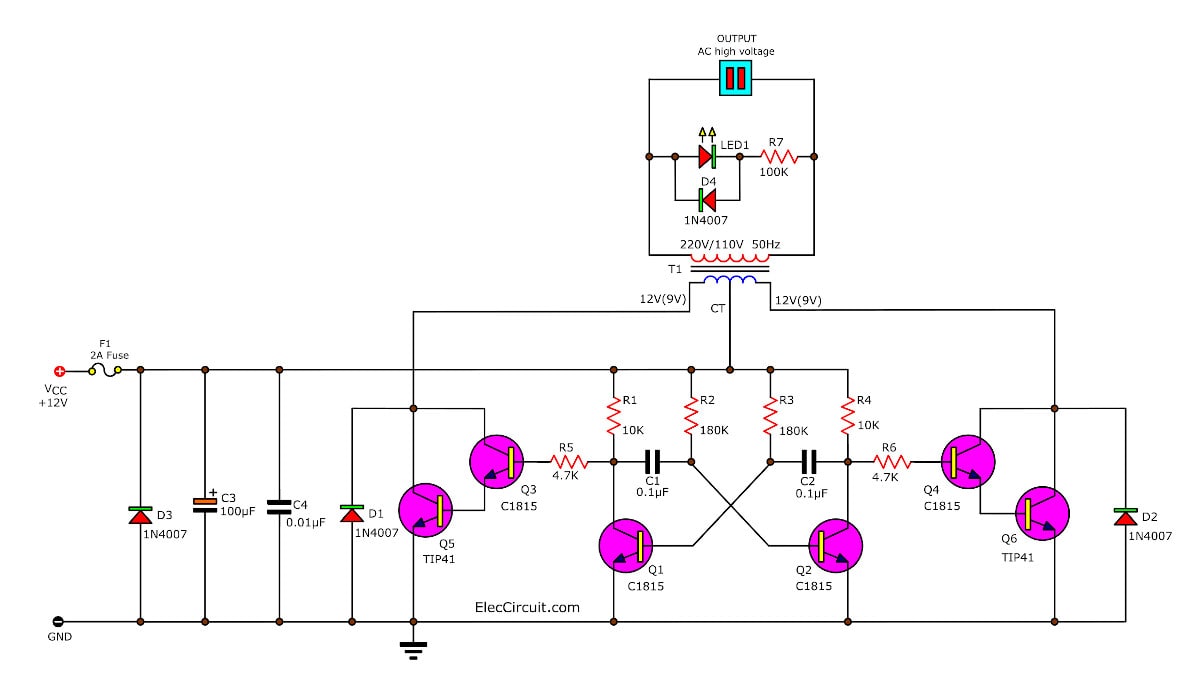
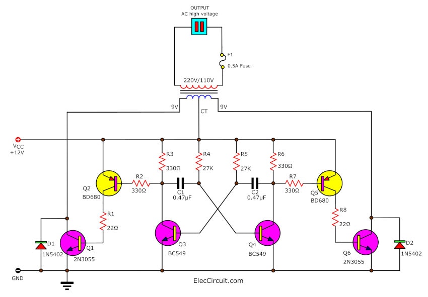
In Figure 8 is perfect circuit, to adding efficiency of this project so I add many parts in the perfect circuit.
Figure 8 The perfect 30watts inverter circuit using 6 transistor.
– D1,D2 are diode protect noise from working of transformer. I choost an 1N4007 (1A-1000V).
– D3 is diode protection if connected in wrong polarity. The negative voltage will flow through D3 instead. Makes circuit safe. But D3 may be short and F1-fuse blown instead.
– F1 is fuse protect over current 1A and in case of wrong polarity F1 also blown.
– LED1 is power on display when have the power : 220V 50Hz completely. The R7 acts to reduce current to LED1. And there is D4 set the polarity to LED1 appropriately
The building and how to use its.
To begin with we have to many parts below.
The parts list
Semiconductors
Q1-Q4: 2SC1815 or other equivalent transistors
Q5, Q6: TIP41 or others equivalent transistors
D1-D5 Diode: 1N4007 or equivalent
LED1-LED as you like
C1,C2: 0.1uF 100V, Mylar capacitors
C3: 0.01uF 100V, Mylar capacitors
C4: 100uF 25V, Electrolytic capacitors
0.25W Resistors, tolerance: 5%
R1,R4: 10K
R2,R3: 180K
R5,R6: 4.7K
R7: 100K
F1: Fuse 1A
T1: Transformer, 0.5A, 12V CT 12V
Heat sink,PCB,and others parts, etc.
Then make PCB as Figure 9 and assemble many parts on PCB as Figure 10
I think many people visiting this site regularly. And Building projects have similar characteristics. I would not advise you how to create this project.
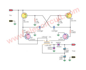
Easy 2N3055 inverter circuit, 12V to 220V 50HZ
This is 2N3055 Inverter circuit ,It Converts 12VDC to 220VAC Output 180W. Use easy Circuit Square Wave Oscillator Generator 50Hz.
So Boost up Current High using 2N3055 Drive Transformer output 220V 50HZ From Voltage Supply 12V 10A.
This circuit is converter to use to charge DC12V from the lead-acid batteries to AC 250V for use in a car, Boats or mobile homes. There are the output power There are the sufficient power to the small electronics such as a lamp or electrical soldering iron. In circuit use only six transistors, transformer and a few electronic parts. So it is easy to build and cheap, too.
How it works
The Q3(BC549) and Q4(BC549) both are the stable multivibrator (AMV) has output is pulse square wave from about 50 Hz. They will alternately inductor current.
-And the power section also works on push-pull form.
– When Q3 induct current will have the current flows through Q2, making Q1 connects the half coil circuit of the primary transformer with the 12V drop across voltage from battery.
– When Q4 induct current, transistor Q6 will connects the primary coil circuit another one to drop across the replace 12V voltage.
– If you use the transistor in the output section to be number: RCA 40411 will be has the current flows through the primary coil in each time is 10 amperes. To power output (Way secondary coil) is 180 watt. However, if the number 2N3055 power output will be have a 90 watt.
How to uses
– Because transistors being used in saturation. Therefore, it must be held on a large heat sink. there is the cooling fins that size over than 100mm up and also multiple fins. And If using transformer is triodes core, it makes a smaller size.
– The circuit is small, because have a little device makes do no adjust to a sine wave. Thus the wave output will be a square. Which may be a result of some electrical appliances, such as, dimmer lights and electric motors, may be will not work. Because it is designed to be used with a sine wave power, and is not recommended for use with color TV and video or audio tape.
Note: This circuit worked well please watch video below.
Thanks.
GET UPDATE VIA EMAIL
I always try to make Electronics Learning Easy.

I love electronics. I have been learning about them through creating simple electronic circuits or small projects. And now I am also having my children do the same. Nevertheless, I hope you found the experiences we shared on this site useful and fulfilling.
i wont 12to 240 inveter daigeram sipel
Hi, R4 and R5, how many WATT???
Hi,
It is very hard to find 1N5402 diode and BD680 transistor. Is there any substitution? After all i do have a 12-0-12 5A transformer . Can i use that transformer in this circuit?.
What are the ampere of the 9-0-9 or 12-0-12
hi..I wont a diagram of 6v to 220…tnx
what is f1????
o capacitor do inversor de 180w é polarizado
F1 is fuze
thank u of this good circuit.
Figure no 7 circuit tried but failed. I manage to get Ac 8 volts only and 47.5 HZ. Please explain to me why it has happened.
Hi, Raj
You should use the Transformer 12V CT 12V.
hii admin.. I want to design an automatic inverter which can drive at least two cfl lights..please will u send me a simple circuit diagram and components required on my e-mail id…
I will try it ,let u know ,thank you
hello sir,
can i use the circuit given by you to glow the cfl l
hi sir i have very simple inverter atleast two lights 12v transformer 12vbattery TIP3055 transister please very eassey inverter diagram please
Hi,Swapnil
Thanks for your feedback.
Hi,mukesh
Thanks for your feedback.
Hi,Arun
Thanks for your feedback.
Yes, you can use it TIP3055 is power transistor same 2N3055 but easy to use.
Please look at : https://www.eleccircuit.com/transistor-inverter-circuit/
If you need other inverter circuit projects.
Sir,
In your description of the circuit where you have very nicely explained the working and calculations. you have set the wattage as 10 watts. still your title says 30 watts. Is it a typo error. I understand the the same circuit can be used to make a 30 watt inverter by suitably changing the power transistors and appropriate transformer. THE CIRCUIT DESCRIBED IS A 10 WATT INVERTER. RIGHT?
Hi,ravindra Kashyap
Thanks for your feedback.
Admin pls help me. I want to design the ckt using a 6v battery and 6-0-6 , 2 amp transformer.. Will it work?
Your site is awsome.
Hi,Prits
Thanks for your feedback.
You can use 6V battery and 6V ct 6V transformer.
but you need to new finds all parts.
For example: R1-R5 and C1,C2
If your projects finish please share photo for me.
or at email : [email protected]
Hi sir,
I want use this with 9v battery . Plz send me to diagram.
hey momename, will u provide a inverter ,link. I wish to drive a 21 watts tube light which is best and cheaper.. Its urgent dear…
i want to build a low cost inverter.. Give the link
Hi,Prits
Please see :https://www.eleccircuit.com/inverter-12v-to-220v-100w-transistor/
This worked.
Thanks for your circuit. I hope i will find the components to build one thanks again.
Sir,
What is the efficiency of this circuit.
If I need to power an allout mosquito matt of 6watts/230VAC for 10 hrs, what will the mAH of the battery be and if so will the balance unused 4 watt be wasted?
If you finalize the battery 12V/mAH(?) then can you please design an efficient charger to charge the same in less than 2 hrs.
Thank you
i like it
What is the ampere rating for battery used..?
What is the ampere rating of battery used…? 12 v battery is fine.. Bt what about amere rating..? Does it has any effect on the circuit…?
What about ampere ratings of battery used…? Does ampere ratings.. Effect the… Circuit working…?
Hi….
I am iIranian.
Tank you….
The best.
what is the amps of the 12~0~12 transformer
Hi surya,
Yes you can use 12volts transformer and current about 2-3A for hobby only.
But please look at these circuit better.
https://www.eleccircuit.com/inverter-12v-to-220v-100w-transistor/
https://www.eleccircuit.com/how-to-build-the-200-watts-home-inverter-projects/
https://www.eleccircuit.com/500-watts-mosfet-power-inverter-using-sg3526-irfp540/
Hi sir,i have 12v5A automobile battery i use this battery to this 180w inverter?
what is the amps of the battery?
Sir,can i use 12v 7ah battery?
thanks alot for u and for ur site
how to calculate the output watts?
Thank u for the circuit , i hav tryed to simulate the circuit and its not working please help? Especially with transistor BD680 , is there an equivalent i can use and when i try to test the astable circuit both the transistors BC549 are not conducting..thanks for your help.
Can i use 5amp transformer for 60w o/p
Help me plss
Hello, I put the circuit just as in the diagram but it didn’t work correctly and so I wanted to ask the amperage of the transformer because am using a 9-0-9V primary and 230-240v secondary transformer rated at 4A primary? Thanks for the help…
What is The value of the capacitor?
please can I use 200k instead of 180 and 14 k instead of 10k?
please can I increase the power using the same oscillator? and how do I do that.thanks for your time sir
hello i try to work out the same like your design i think still struggle is really working because the frequency is ok but i do not find the exact on your clip what i seen
can I use any other capacitor instead of mylar capacitor?will it be a problem?
i need help to make inverter using transformer without ct. thanks
Hi dede
Do you DC to AC inverter circuit without IC?
This circuit is good. Or other circuits
https://www.eleccircuit.com/simple-transistor-inverter-circuit-diagram/
https://www.eleccircuit.com/dc-to-ac-converter-circuit/
https://www.eleccircuit.com/inverter-12v-to-220v-100w-transistor/
They are easy to build and cheaper.
Good luck and keep soldering.