This is a telephone line status indicator to prevent the hearing others talk on the phone accidentally and a Protection to making phone calls simultaneously.
The telephone is a communication device that enables to communicate with each other, although it is far or near. Formerly, one phone number. Be used with only one phone.
But now one phone number will connect 2-3 phones together. This peripheral Most are installed on each floor or various rooms. Making when use either telephone by Others will not know, which causes gaffe. Without implicitly intend.
Incidentally, If the telephone line lack on the way. Might think that the phone damage, and buy a new one. therefore modify incorrectly.
We can solve this problem with this project. It can show phone usage, or the phone line by LED making can to see clearly. A model of the circuit is small. And does not require batteries.
The working principle
In normal operation, the phone line while does not Pick up the phone will have DC voltage about 48 volts. But if picking up the phone voltage will drop down under 10 volts (4-8 volts).
This is the basic principle of the phone and the source of the circuit in Figure 1 for this project.
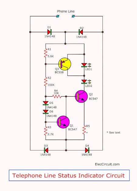
Figure 1 The telephone line status indicator circuit
In the circuit, while also does not pick up the phone, the voltage of 48 volts will reach the rectifier circuit that includes of the diode D1-D4 to acts as setting voltage correcting and also as the power supply voltage.
This section voltage will make transistor Q1-Q3 works so results to LED2 glow up. But LED1, not light.
Because when the Q3 working causes the emitter lead and collector lead of circuit joint together. Thus, like a short LED1 there.
This condition is so as checking the phone line status or lack of Short.
Then we are picking up the phone, The voltage will drop down to about 4 volts to 8 volts, makes Q1 and Q3 stop working, both LED1 and LED2 will glow.
Just as we know that have using the phone occurs.
How to builds
We start to make a PCB as Figure 2 before. Which is Actual-size of Single-sided Copper PCB layout.
Then, prepare the equipment and as the part list below. Next soldering all component into PCB as Figure 3 before. Soldering equipment should lower to higher solder is simple and beautiful.
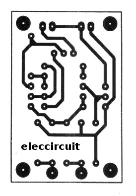
Figure 2 Actual-size of Single-sided Copper PCB layout
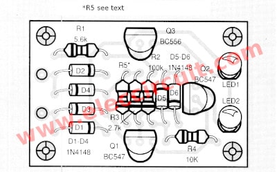
Figure 3 The components layout.
Application
Form connections for use is easy, Just connect to across the phone line. If normal, LED2 ( Green) will glow to indicate that the phone ready use it any time. Then try picking up the phone, You can see that LED1 (Red) caught up, To indicate that With the use of the phone.
For the brightness of both LEDs, will a relationship between. The resistance of R5 and the quantity of phone that connection. If two use R5 of 270-330 ohms. But three use 390-470 ohms. Just this, it is complete.
The parts list.
Resistors 1/4W +5%
R1: 5.6K
R2: 100K
R3: 2.7K
R4: 10K
R5: see in the text.
Semiconductor
D1-D6: 1N4148___75V 150mA Diodes
LED1: Red – LED
LED2: Green – LED
Q1, Q2: BC547, 45V 100mA NPN Transistor
Q3: BC556, 45V 100mA PNP Transistor
Others parts
telephone line
The Universal Board. (Perforated board)
GET UPDATE VIA EMAIL
I always try to make Electronics Learning Easy.
Related Posts


I love electronics. I have been learning about them through creating simple electronic circuits or small projects. And now I am also having my children do the same. Nevertheless, I hope you found the experiences we shared on this site useful and fulfilling.
thanks for sharing this simple line status indicator
use R4 resistor of 4k instead of 10k …….
Hi,
Thanks for your sharing.
Did you use R4, it is 4K? Does it work well?
I ask you too much. Sorry! I’m just excited that you’ve tried this circuit.
Bonjour.
Pourriez-vous me fournir le PCB de “l’indicateur d’état de la ligne téléphonique”?
Hello. Could you provide me with the PCB of the “telephone line status indicator”? Thanks a lot.
Hi
Thanks for you visit my site again.
The PCB size is 1.370×1.975 in on 200 DPI per inch on a printer.
Have a good day.
I want a circuit when I am on phone call on landline telephone if someone call to the same phone any led indication circuit to know some person is getting engage