An inductor, also known as a choke or reactor, is a simple passive electronic component. It functions similarly to a capacitor, but instead of storing energy in the form of charges, it converts electrical current passing through it into a magnetic field. Then, when its magnetic field contracts, it releases the energy back into the circuit in the form of electrical current.
Inductors, along with resistors and capacitors, are the three basic electronic components. The inductors seem to be the most complex out of the bunch because of the involvement of electromagnetism. But in practice, an inductor is not that much harder to use than the other two, as long as we know its basics. Let’s learn about the inductor, how it works, and how to use it.
What is an Inductor
As mentioned earlier, an inductor is a passive electronic component with two leads. Its construction usually comprises copper wire wound onto a core in a coil fashion. The core can be of two types: an iron core, usually a high-permeability ferromagnetic material such as ferrite. An air core, which does not have a core at all, or sometimes has a non-ferromagnetic material like paper or plastic as a core.
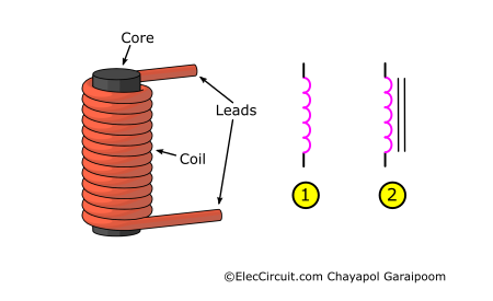
An electronic symbol of an inductor in a circuit schematic is a symbol indicating a coil, or a simplified version of it, as seen in the image above. Notice that some have two straight lines on top of them. This indicates that the inductor has a core, while one that lacks these lines does not. An inductor core comes in various shapes and sizes, such as rod and circular designs, as well as small enclosed ones, as shown below.
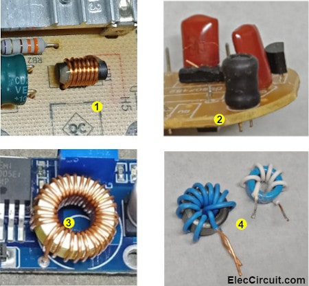
The images above show some of the most common inductors we see. The first (1) is the most basic design: a wire wound around a cylindrical core. The second (2) is a DIP radial power choke, while the third (3) is a toroidal magnetic core inductor. Finally, there are the fourth (4) DIY metal core radial inductors.
How an Inductor Works
Simply speaking, an inductor converts electrical current into potential energy and then stores it. But rather than storing charges like a capacitor does, it retains potential energy in the form of a magnetic field surrounding the coil. You might be aware that current flowing through a wire creates a magnetic field around it.
An inductor also uses this principle. By coiling many wires closer together, their magnetic fields combine, thus creating a single, stronger magnetic field. As this magnetic field shrinks, it will induce a voltage onto the inductor. This causes electrical current to flow in the circuit.
An ideal inductor will also allow DC to pass without any resistance. However, real inductors may still have some DC resistance due to wire resistance. Furthermore, when there is a change in current, the amount of potential energy stored within the inductor changes, either increasing or decreasing.
Current and Voltage of an Inductor
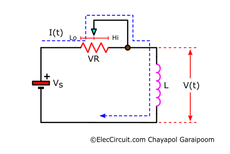
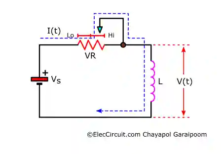
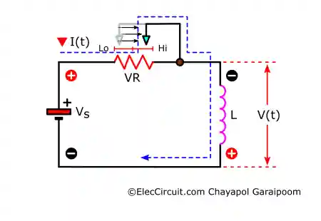
Let’s understand the current-voltage relation in a circuit. Start by creating an imaginary circuit consisting of a power source, a potentiometer, and an inductor. The voltage of an inductor is a product of its inductance and the rate of change of its current. Therefore, we will use the potentiometer to adjust the current. Lo and Hi atop the potentiometer indicate low- and high-resistance values, respectively.
Next, let’s take a look at the equation for the voltage of the inductor at a specific point in time:

Where V(t) is the voltage across the inductor at a point in time, L is the inductance of the inductor in units of henry (H), and dI(t)/dt is the rate of change of the current in amps per second (A/s). Both the voltage and the rate of change of current are dependent on time, whereas the inductance is not.
To begin with, let’s assume that we set the resistance value of the potentiometer to a very high value, so that only a small but constant current flows through the inductor. Applying the equation from above to the inductor results in the following:

Plugging current and voltage into an overlay graph yields:
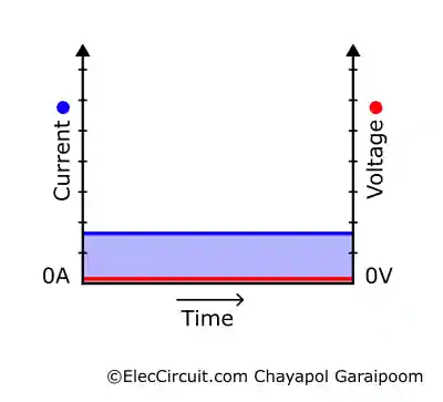
We can see that since the current does not change (dI(t)/dt = 0A/s), the voltage will remain at zero for the entire duration, regardless of the inductance value. However, when we gradually decrease the potentiometer resistance, the current flow begins to increase at a steady rate. We assume that the rate of change dI(t)/dt is perfectly linear.
Current Increasing
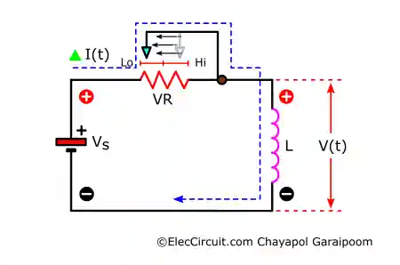
There is now a voltage across the inductor. According to Lenz’s law, the polarity of the induced voltage opposes the change in current. The induced voltage will try to resist the changing current.
Thus, in this situation, the positive terminal of the inductor is oriented in the same way as the positive terminal of the power source, resisting the additional current, as shown above. We could also think of it as the inductor “charging.”
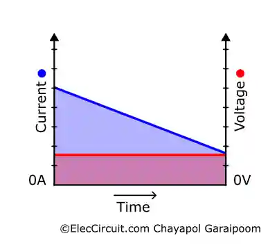
Another way to look at it is that the inductor converts the electrical potential energy from the increasing current into magnetic potential energy. As a result, as the current increases, the magnetic field expands, more electrical potential energy gets converted into magnetic potential energy, and the magnetic field exerts the opposite voltage. Then, plotting the result into the same graph shows the following:
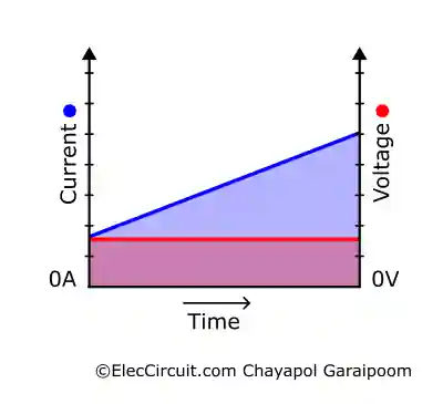
The graph above shows that the voltage remains constant while the current increases linearly throughout the duration.
Current Decreasing
Furthermore, this same process also occurs when we linearly increase the potentiometer’s resistance, and the current rate of change dI(t)/dt is negative or the current is decreasing. Assuming that the decreasing rate is the same as the increasing rate earlier, the voltage would also be the same.
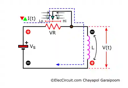
However, Lenz’s law states that the polarity of the induced voltage opposes the change in current. So when the current drops, the induced voltage attempts to maintain the same current flow. As a result, the negative terminal of the inductor will be oriented to the positive of the power source to increase the current flow, as shown above. Which we could also think of as the inductor “discharging.”
The graph is the same since the voltage is the product of the rate of change and inductance; a positive or negative rate of change does not affect the voltage as long as the rate is the same.
Current Fluctuating
Lastly, consider this example: where we adjust the potentiometer up and down randomly every second or so to simulate alternating current. Now the rate of change of the current is no longer linear as before; instead, it fluctuates up and down rapidly.
Because the rate of change over the entire duration is non-linear, we can only use the previous equation from one point of change to the next or when we adjust the potentiometer. Each of these local current changes is analogous to the linear graph’s total current change from earlier. The current-voltage overlay graph will appear along the following lines:
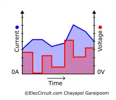
The polarity of the inductor voltage still changes whether the current is increasing or decreasing. In the part of the graph where the current is increasing, the inductor polarity will be the same as the source, opposing the incoming current. Whereas in the part where the current is decreasing, its polarity will be the opposite of that of the source, aiding the incoming current.
Nevertheless, in reality, this entire process happens instantaneously, too quickly for humans to meaningfully understand. And it is definitely not because of us manually adjusting a potentiometer.
But the takeaway is that the voltage across an inductor is the product of its ever-changing current and its inductance. The induced voltage opposes the changes in current. Additionally, from the original equation, we know that the inductance acts as a multiplier for the rate of change of the current. But what is inductance anyway?
Inductance (L)
The inductance (L), measured in units of henry (H), is the main identifying value of an inductor. Simply put, inductance describes the amount of potential energy a conductor can store in its magnetic field per unit of current. Higher inductance means a bigger magnetic field and more potential energy stored within.
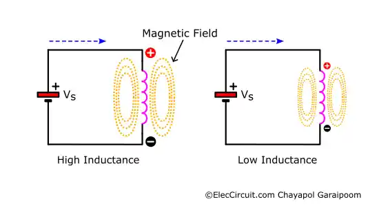
To put this into perspective, when a high-inductance inductor is subjected to a high current, the magnetic field and thus the opposing effect (reactance) of the induced voltage would also be high. When a low-inductance inductor is subjected to the same current, the magnetic field and induced voltage are lower, allowing the current to pass more easily.
The inductance of an inductor depends on its construction: core material, coil density, number of coil winds, and diameter. An inductor with a high-permeability material core, such as a ferrite, often has higher inductance. Hypothetically speaking, an inductor with 25 turns around a metal core may offer the same inductance as one with 100 turns around an air core.
Reactance (XL)
The resistance produced by the induced voltage to the current that induces it from earlier is referred to as inductive reactance (XL). Similar to a resistor’s resistance, we also measure an inductor’s reactance in units of ohms (Ω). The reactance is:

Where L is the inductance and ω is the angular frequency (ω = 2π × normal frequency) of the inductor’s input AC. We will see that the inductive reactance (XL) is proportional to the input frequency. Meaning that the higher the frequency, the higher the reactance.
Quality Factor (Q)
The Q, or quality factor, is the value indicating the efficiency of each inductor. A higher Q value means lower energy losses during the induction at a given frequency and, thus, is closer to the perfect inductor. However, in reality, an inductor suffers energy loss in dozens of ways, such as core losses and outside factors affecting its magnetic field.
Factors such as core material permeability also directly contribute to the quality factor of a specific inductor. For instance, an inductor with a high-permeability material core may have a high Q factor at a lower frequency. But when the frequency increases, the Q factor may drop drastically because of core losses.
Another important value is the DC resistance (DCR); it is one of the specifications, alongside inductance and current. As the name suggests, it is the inductor’s resistance against direct current. The inductor’s quality factor is also defined as the ratio of the inductive reactance (AC resistance of inductance) to its DC resistance at a specific frequency:

L is inductance, R is DC resistance, while ωL represents the inductive reactance (also known as XL). If the ratio between L and R remains the same, the Q factor would increase at the same rate as the frequency. However, in practice, R would usually change depending on the frequency. Whereas L may vary depending on the coil parasitic capacitance or the evenness of core permeability.
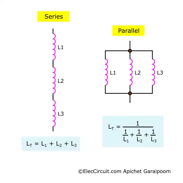
Inductors in Parallel & Series Networks
When connecting multiple inductors together into a network, their electrical properties mirror those of a resistor. In a parallel network, the total reciprocal inductance is the reciprocal sum of every inductor. Whereas in a series network, the total inductance is the sum of every inductor.
However, because a working inductor has a magnetic field surrounding it, an inductor may exert magnetic force on nearby inductors, which is known as mutual inductance. If the inductors have the same polarity, the inductance may combine into a higher value. But if the inductors are opposite polarity to, the magnetic field may cancel, resulting in a decrease in inductance.
It is quite complex, but as a rule of thumb, it is generally recommended to keep inductors far apart from one another to avoid conflicting magnetic fields. But with that being said, this mutual inductance is also the primary concept behind how a transformer operates.
Important Values When Buying an Inductor
When purchasing an inductor from a manufacturer or reseller, we must consider several key specifications. The example table below displays an inductor sold by the seller online. Notice that they all have the same dimension, but the rest of the specifications vary.
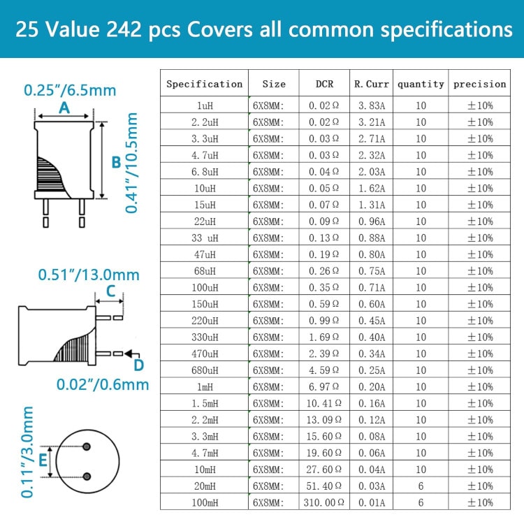
Image credit and affiliated link: https://amzn.to/45VCZGX
First is the inductance in the units of H. In this specific table, it starts from 1uH to 100mH (higher values are also available).
Second is the DCR (direct current resistance) in the units of Ω. Because inductors in the table shared the same design, DCR is proportional to the inductance.
Third is the rated current in the unit of A. It is the current these inductors can withstand as rated by the manufacturer.
For example, when purchasing an inductor for use in a buck converter that has a 3A output current and requires an inductance value of 33uH. If we are buying based on the table above, the 33uH unit has a rated current of only 0.88A. Therefore, we would need to find a larger unit with the same inductance value because a lower-current one cannot substitute a higher-current one.
Side note: similar to other electronic components, an inductor is sold with an E series of preferred inductance values, usually E6 or E12. Although higher inductance units may also get rounded up further, for instance, 20mH or 40mH.
Typical Inductor Applications
We use an inductor in many electronic applications, especially switching power supply circuits, DC Buck converter, filters, LC circuits together with a capacitor, and more.
In signal filter applications, an inductor will allow DC to pass through while blocking AC. Similarly, in an AC circuit, an inductor can also be used to decouple DC by acting as the shortest path for DC to flow to the ground.
In switching-mode power supply applications, an inductor stores energy and then releases it during the “low” switching period. Furthermore, in an LC circuit, an inductor connects to a capacitor to either oscillate or to filter out a specific frequency signal.
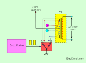
We could also think of a transformer as another usage of an inductor. It uses the principle of mutual inductance to induce energy from one circuit to another disconnected circuit. A transformer is just two separate coils wound around a single common core.
But, for us in particular, we use inductors the most in DC converter applications, such as buck converters and boost converters. Below are some of the circuits we built with the help of an inductor in the past.
Example Circuits that Utilize Inductors
- 4 Buck Converter Circuits | Step-down Converters
- 3.7V to 5V Boost/Step-up DC converter circuit
- 12V to 15V-24V Boost Converter Circuit
- 3V | 1.5V Switching Regulator circuit
- LM2596 circuit voltage regulator and LM2673 datasheet
- Simple 1.5V LED Torch circuit
- LM2577 Boost Converter circuit | Step up | Datasheet | Pinout
- You could also check out our article on recycling inductors from broken electronics here.
GET UPDATE VIA EMAIL
I always try to make Electronics Learning Easy.

I love electronics. I have been learning about them through creating simple electronic circuits or small projects. And now I am also having my children do the same. Nevertheless, I hope you found the experiences we shared on this site useful and fulfilling.