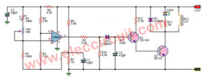
This is digital temperature meter circuit that has High the accuracy temperature measurement. In the Measurements temperature by diode 1N4148 and Dfferential Temperature Relay Switch by IC 741 we use diode is sensor which saving but average quality. This projects we use the LM335 and LM135 both are sensor IC designed specifically for this function.
The LM335 is features can run at temperatures from -40 to 100 degrees Celsius. If you want to work at higher temperatures than this, you will need to use the LM135 can be used at temperatures of -55 to 150 degrees Celsius
The important feature of the LM335-IC there are the voltage value drop across IC of 2.73 volts at temperatures 0 degrees Celsius and voltage will change of 10 mV per changes in temperature 1 degrees Celsius.
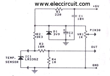
The figure 1 is temperature sensor circuit using LM335
As shown in Figure 1 is our digital temperature sensor circuit using LM335 which can lead to the use with the digital voltage by using very little equipment.
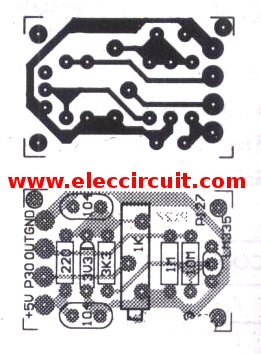
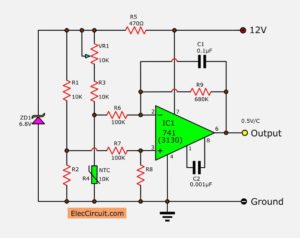
Figure 2 is pcb of circuit above
and the figure 2 is PCB and Positioning accessories on PCB of this digital temperature sensor circuit
The output of this circuit is connected to the digital meter at the original input and pin 32 (low input) Which was connected to the ground by using a knife to cut the copper off the ground.
How to build this project
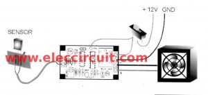
If you want to build a complete Digital temperature meter project can be viewed in the figure 3 We combine all the circuits in the same circuit and can see PCB in Figure 4 and in figure 5 is a positioning device of this project.
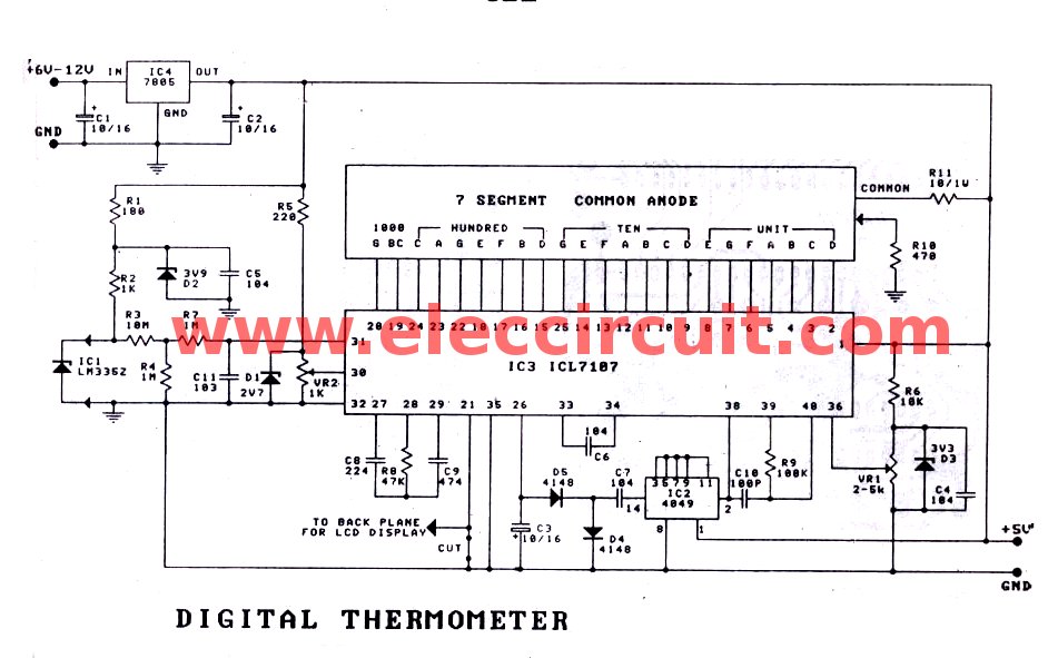
Figure 3 The PCB of this projects
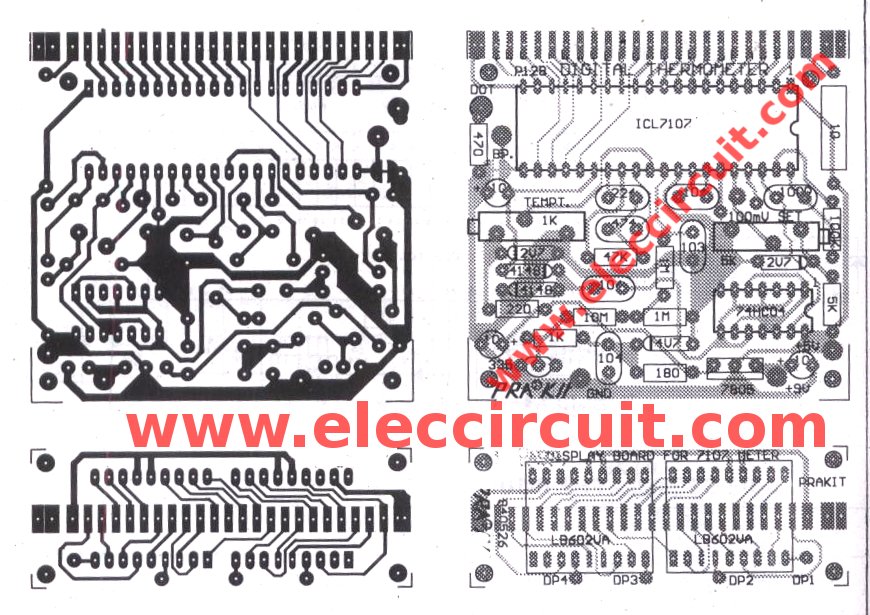
Figure 4 put all parts correctly
In making to put all parts to PCB correctly
Diode and Electrolytic Capacitors must be particularly careful not to reverse the polarity is strictly prohibited.
When assembly device in the circuits is finished can supply the power source to this projects. If you have dc regulation power supply of 4.5V or 5 volts then can connect to the 5 volts point derectly.
But if not have you may be connect a voltage supply to circuit between 6-24 volts into a input pin of IC-LM7805 regulator Will be supply voltage of 5 volts as needed.
Customization.
The first step in the tuning circuits. Adjust VR1 until the voltage at pin 36 is 100mV. Then, looking for thermometer. or Standard thermometer. How to see the current temperature.
Then adjust VR2 until the digital meter reading at such a standard temperature.
Detailing of parts (simple list)
IC1: LM335 Precision Temperature Sensors
or LM135
IC2: CD4049 Hex Inverting,Non-Inverting Buffer
IC3: ICL7107
1/4W +/- 1% Resistors
R1: 180 ohms
R2: 5K
R3: 10M
R4, R7: 1M
R5: 220 ohms
R6: 1K
R8: 47K
R9: 100K
R10: 470 ohms
R11: 10 ohms (1W.)
VR1: 1K Linear Potentiometer
VR2: 2K Linear Potentiometer
IC4: LM7805 is 5V dc regulator IC
D1, D3: ZD 2.7V, 0.5W Zener Diode
D2: ZD 3.3V, 0.5W Zener Diode
D4, D5: 1N4148, 75V 150mA Diodes
Electrolytic Capacitors
C1, C2, C3, C4: 10uF 16V
C7: 1uF 50V
Polyester Capacitor
C5, C6: 0.1/63V
C8: 0.22uF 50V
C9: 0.47uF 50V
C10: 100pF
C11: 0.01uF 50V

I love electronics. I have been learning about them through creating simple electronic circuits or small projects. And now I am also having my children do the same. Nevertheless, I hope you found the experiences we shared on this site useful and fulfilling.

we r not getting -ve voltage frm 4049
Hi,
In schematic digram, D2=3V9 and D3=3V9 ;but
In the part lists,They seem D2=3V3 and D3=2V7
Which one is correct? Could you give information pls.
B.rgds,
Suna
schematic and pcb layout complately different. 74hc04ap is 14 pin, 4049 is 16 pin and different vcc-gnd in. this circuit is compaltely wrong. do not let this guy broadcast any circuit in anywhere.