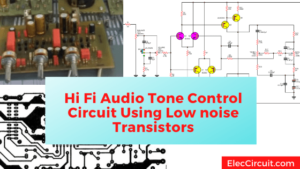
I am going to show you learn LM1036 or LM1035 Dual DC Tone/Volume/Balance control Circuit. Why use it? How it good? Cold down Read below you will get an answer.
We know that the audio system is beautiful. Because it has an excellent preamplifier tone control circuit.
It can control the frequency of the audio signal from 20Hz to 20KHz.
There are many types such as passive tone, active tone, and equalizer. It is another type of tone control as well.
Why should use the DC tone control circuit?
We know better than a normal tone control circuit, use a resistor to raise the frequency level in various audio frequencies ranges.
But now we will use active tone control using DC voltage to control the amplification of each frequency band.
This way we still use the potentiometer as before. But it will be better and more economical. how? Please continue reading.
How it works
The operation of this DC tone control circuit. Most will be included in only one IC-LM1036. Which is produced as the tone control circuit in particular. We have a circuit that is smaller and helps to save more than other circuits.
LM1036/LM1035 Datasheet
It is a Dual DC controlled tone (bass/treble), volume, and balance circuit for stereo applications in-car radio, TV, and audio systems.
LM1036 belongs to the National Semiconductor. This IC will include sub-circuits, everything is within it. So we just bring a few external devices, so we get a circuit that can work well.
An additional control input allows loudness compensation to be simply effected.
LM1036 Pinout
See below, block diagram, the functions of each leg within the IC, and LM1035/LM1036 pinout.
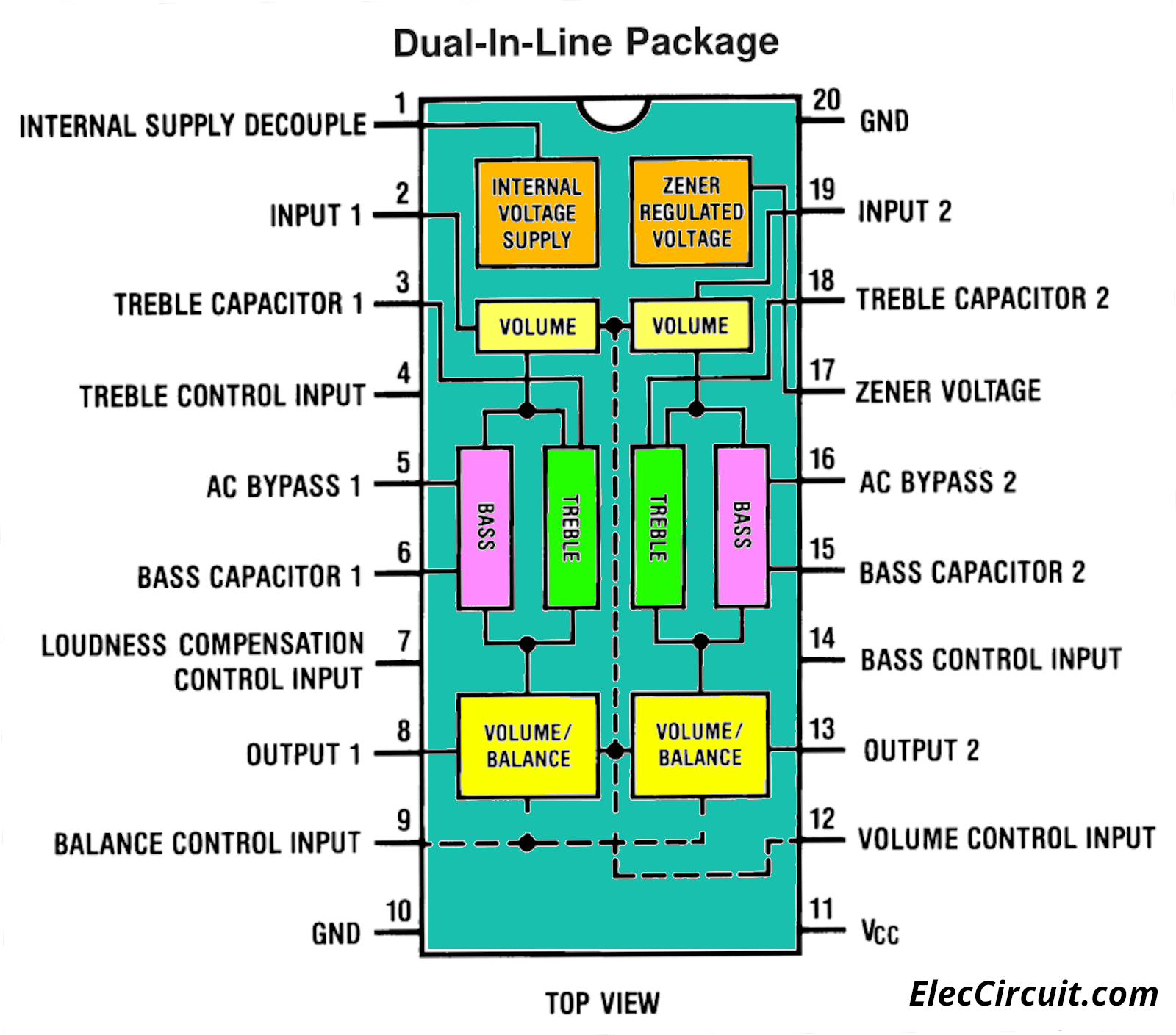
We will consider points of interest.
Four control inputs provide control of the bass, treble, balance, and volume functions through the application of DC voltages from a remote control system.
Alternatively from four potentiometers. Which may be biased from a Zener regulated supply provided on the circuit.
Each tone response is defined by a single capacitor chosen
to give the desired characteristic.
Recommended: Learn Basic Electronics
Features of LM1035 VS LM1036
- Tone control, ± 15 dB typical
- Wide supply voltage range, 9V to 16V
- Large volume control range, 75 dB typical
- Channel separation, 75 dB typical
- Few external components required
Detail above LM1035 VS LM1036 is the same. But both are different here.
- Low distortion, 0.06% typical for an input level of 1Vrms for LM1035, 0.3Vrms for LM1036.
- High signal to noise, 80 dB typical for an input level of 1 Vrms for LM1035, 0.3 Vrms for LM1036.
We will see that LM1036 is better than LM1035. Which one do you choose?
The working of the circuit
Then, see the used circuit below. Although there are many details in the circuit. But do not worry, we will gradually disassemble one by one to learn together.
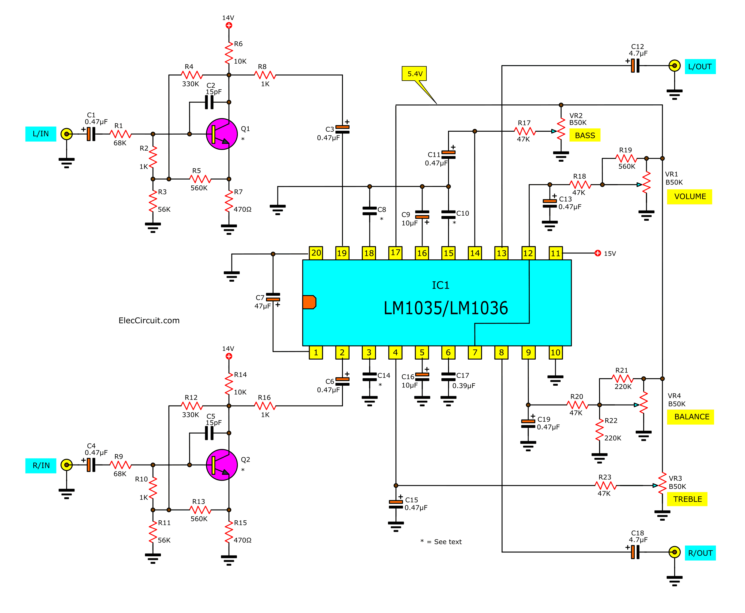
Beginning with low-strength audio signals such as tuners coming to the inputs of the circuit.
And there is coupling by C1 (C4) through R1 (R9) to the input pin B of Q1 (Q2), which acts to increase the signal strength to rise. They work as a simple preamplifier circuit using a transistor.
Preamplfier

There are C2 (C5) to reduce transient. And, The Bias and divider resistor, R2-R7 (R9-R15) is the bias working point for Q1 (Q2). After that, the signal comes out through pin C through R8 (R16).
Then, coupling through C3 (C6) to input pin 19 (2) of IC1. And everything will be done by IC1.
What is more?
Tone control
See in circuit diagram we will focus at the tone control section.
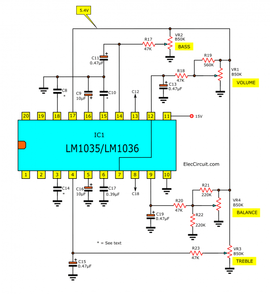
Boot and cut bass and treble sounds are possible by VR2, VR3. And VR1 for turning the volume up and down. And VR4 for balance adjustment.
Which these potentiometers are not used as a passage of audio signals. But will increase or decrease the DC or divider voltage.
The DC voltage will control the various working pins. In which pin 17 of IC1 will give a control voltage of 5.4V. This voltage will be constant at all times.
And This voltage will control BASS control using VR2. It is adjusted voltage up and down. See at the middle pin of the potentiometer VR2 has the voltage coming through R17. It will limit the current to the BASS controller pin.
In addition, volume control pin, Treble control, and balance control work the same way.
The balance control
The most important is the balance section, if using only one volume, the balancing will not be true. Because the value of the potentiometer is not really linear.
So, we use R21, and R22 to make true balancing.
Filter the ripple
The C7 is a filter capacitor for the voltage inside the IC1 and capacitors C11, C13, C15, and C19.
They help to stabilize the voltage that has been controlled by the 4 potentiometers so that they do not fluctuate. Because if not filtered then the sounds signal will ripple as well.
Loudness control
For pin 7 will be loudness off, it means the loudness has no effect. But can connect pin 7 to pins 12 or the middle pin of the volume control. This will result in loudness on or boosting the loudness.
The output signal of IC1 or this DC tone control circuit will come out of pin 13 and pin 8. Then, coupling through C2(C18) to the output of the circuit.
See Idea: transistors Pre tone control circuits
Power supply pin
Pin 11 of IC1 is the power supply voltage. This IC requires a wide voltage from 8V to 18V.
The IC2 is a DC voltage regulator, 15V. The C1 filters the power supply and helps maintain a constant voltage. And the output voltage obtained from the regulated will pass through Resistor R24 limiting voltage and current as a source of an input preamplifier section.
How to build
After reading the working principle. You may be quite boring. Let’s build this circuit. First, prepare all the equipment before.
Parts you will need
0.25W Resistors, tolerance: 5%
R1, R9: 68K
R2, R8, R10, R16, R24: 1K
R3, R11: 56K
R4, R12: 330K
R5, R13, R19: 560K
R6, R14: 10K
R7, R15: 470Ω
R17, R18, R23, R20: 47K
R21, R22: 220K
VR1 – VR4: 50K Potentiometers
Capacitors
C2, C5: 15pF 50V, Ceramic
C8, C14: 0.01µF 50V, Mylar
C10, C17: 0.39µF 50V, Mylar
Electrolytic Capacitors
C1,C3, C4, C6, C11, C13, C15, C19: 0.47µF 50V
C7: 47µF 25V
C9, C16: 10µF 25V
C12, C18: 4.7µF 25V
C20: 220µF 25V
C21: 470µF 25V
Semiconductors:
IC1: LM1036 or LM1035 Dual DC tone control
Q1,Q2: 2SC945, 50V 0.15A, NPN TO-92 Transistor
IC2: LM7815, 15V 1A Regulator
Note:
CR: Photo DYDZYJ
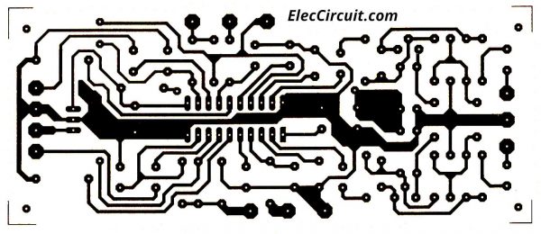
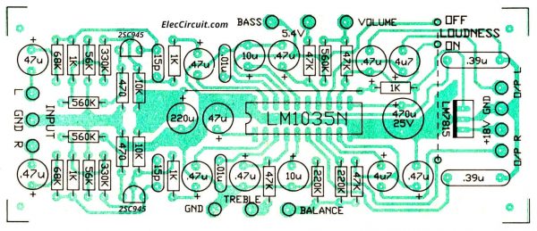
Then, Make a copper PCB layout as below. And see the components layout.
I believe that if you decide to build this project You probably have basic knowledge of electronics.
These skills It is a matter that requires practice and takes a long time to master. Of course, if you are a beginner It’s not something to worry about. If it doesn’t come out well in the first place, it’s a part of your steps. I believe that he will continue to develop.
Poor soldering may cause your circuit to not work.
The most important thing is to be aware of polarized devices such as electrolytic capacitors, diodes, transistors, IC. We must always put the polarity correctly.
I hope you have another good quality pre-tone to listen to beautiful music.
Not only this, but You should also look at this circuit.
TDA1524 | Datasheet | Stereo-tone and Volume control circuit

I love electronics. I have been learning about them through creating simple electronic circuits or small projects. And now I am also having my children do the same. Nevertheless, I hope you found the experiences we shared on this site useful and fulfilling.
Hi, nice work. Do you have by any chance the gerber file to produce this circuit? Thank you.
Hello Sebastian,
Thanks for your feedback. I am happy to hear that. You like it.
But I am sorry, No Gerber file for this circuit.
Thanks
Apichet
Thank you for taking the effort to explain very well the circuit, very helpful for electronic enthusiasts.
Hello Harry,
Thanks for your feedback.
Sir I made this LM1036 pre amp but I don’t know how to connect the volume, balance, base, and treble controllers to the circuit board, could you please explain how to do it.
Is? Is it 6 pin volume controller or 3pin volume controller is needed for this project