I like to learn a power supply. Today let me share, A voltage regulator circuit is very useful. Also, it is fun to learn how it works, principle, design, and a lot of sample circuits.
If you are a beginner. You should look at: The working of Unregulated power supply.
What is a regulator?
Imagine you finished 12V unregulated power supply. But you need the 5V power supply for a digital load. How do?
You should reduce the voltage down to 5V. And It must also be a constant voltage. Even any loads it still has low ripple.
The circuit can do these called “Regulator”.
Types of Voltage Regulators
In general, we use electronic devices to build a voltage regulator. They have a lot of types. But we may put all in basic 2 types of voltage regulators viz.,
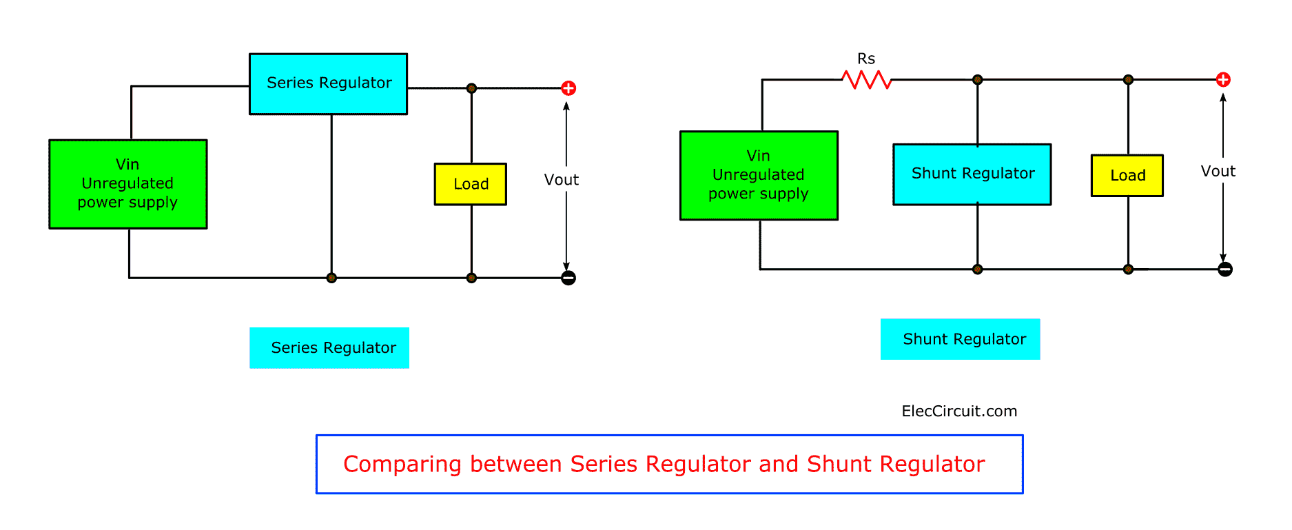
- Shunt voltage regulator
- Series voltage regulator
The shunt voltage regulator—we will place them in parallel with a load. Often use a resistor to reduce the current of all.
On the other hand, Series voltage regulator. We will place it in series with a load.
See in the image to compare it.
Also, sometimes we can divide it into 2 types depending on the output voltage.
- Low voltage—Output lower than 50V. Use Zener diode alone or Zener diode with the transistor.
We called these a transistorized power supply. It can give only a low stabilize voltage. Because the safe value of VCE is about 50V. And if too more voltage it may occur the breakdown of the junction in the transistor. - High voltage—in general, we do not use this level. It is the voltage for more than 50V. Often use to glow tubes in conjunction with vacuum tube amplifiers.
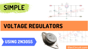
Make: 0-50V 3A Adjustable Regulator Power supply
You may not get an idea. I will gradually explain to you, don’t worry.
There are a lot of ways to build a regulator. We start with “diode”.
Cr: I love to learn English with Electronics blogs and Ebook. I often visit in http://www.talkingelectronics.com/ Mr.Colin Mitchell is a great electronic person. Although I use English as a second language But I can read and understand his content easily. I am excited about this knowledge. I used to study from a teacher when I was a kid. Who do my teachers take that content from?
The diode voltage regulator
The Diode is the simplest regulator.
See in the image below. The output is too low voltage. The resistor(R) passes the current to the diode(D). The resistor is dropping the voltage.
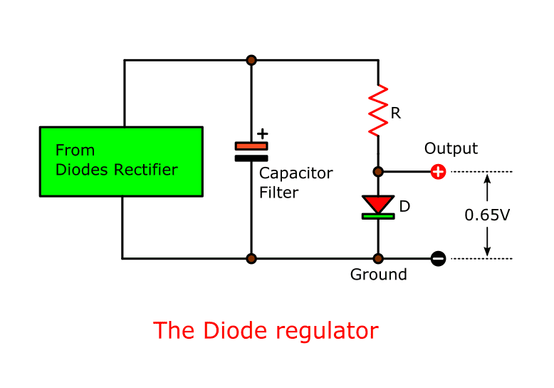
The main idea, If we measure the output voltage is 0.65V at all time. Even the input voltage from the rectifier changes any voltages. There may be 6V, 12V, or 24V.
We called this form “Shunt Regulator”.
The voltage between the diode and the input will drop in the resistor. If more voltage it is a very wasteful circuit.
Why? I will show you more.
Suppose that the input voltage is 12V. And the current all is 1A. So…
The voltage across the resistor is 11.35V. And the wattage is 11.35V x 1A = 11.35W. Too wasteful.
The output power is 0.65V x 1A = 0.65W.
So, most of the power is lost.
Then, we try using 0.2A. And, the output voltage still is 0.65V. But the power at the resistor will reduce to 11.35 x 0.2 = 2.27W only.
How the diode works
Next, we learn more about the diode circuit works. How much resistance of the resistor? I redrew the diode circuit as below.
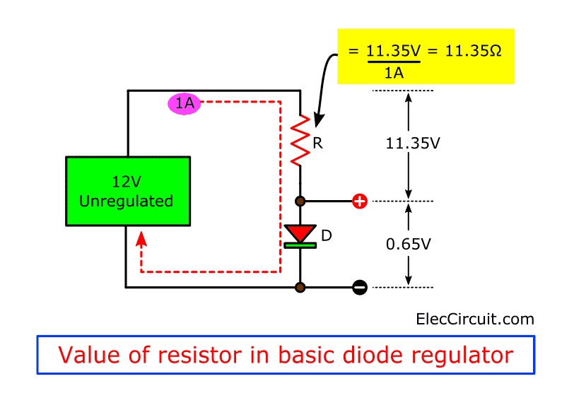
We need the current flow of 1A in the diode. (I = 1A)
So, we need to use a resistor is 11.35 Ω.
Because…
This value gets from ohms law:
The voltage across R = 12V – 0.65V = 11.35V
R = V/I
= 11.35V / 1A
= 11.35 Ω
Testing difference load
Then, we add a 1K potentiometer(VR1) across the diode(D1). The VR1 is like a load. The current will flow through VR1 too. And, a voltage across D1 and VR1 still be 0.65V.
See in the circuit below.
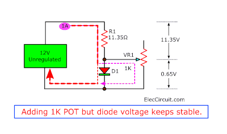
While the first current of VR1 will be 0.001A or 1mA. This means the current through D1 is 0.999A or 999mA.
Next, we start to adjust VR1. More current through VR1. It pulls current from D1. Lastly, the current through VR1 is 0.999A, but D1 is only 0.001A.
As soon As VR1 pass 1.001A current. But the current not pass D1 and regulation will be lost.
The output voltage will drop to 0.64V or lower.
So, the diode will keep the fixed voltage (0.65V) when the current from a few milliamps to 1A
We need 2 functions of the diode regulator:
- Smoothing Voltage—reduce any ripple lowest.
- Stability Voltage— keep the voltage at 0.65V even difference load.
How to increase the output voltage
We can connect a lot of the number of diodes in series as shown in the Figure.
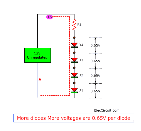
They give more voltage. It is 0.65V per each diode.
If you are not clear. See these:
The voltage dropper using diodes
One diode a reference voltage—in 0-30V 1A variable power supply.
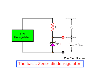
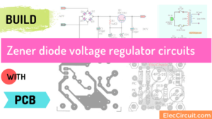
Zener Diode voltage regulator
But it is not comfortable at all. Imagine you want 12V regulator. You need more 20 diodes. How to does it easier?
Use a Zener diode. It is one kind of diodes. We always use the opposite-way to a general diode. The Zener runs with a break down at a specified voltage.
For example, the voltage of the Zener diode is 12V, 5.6V. And the voltage range is 2V to 68V. But you connect it in the same direction like a normal diode. It would drop only 0.65V.
Recommended: Zener Diode Principle working, example circuit usage
These circuits are suitable for small load using a low current.
If you want to learn how to design it. Read more 2 circuits below.
- 5V regulator using low current—use low current for small digital. So easy.
- Dual Zener regulators—Power Supply for Audio Amplifier,multiple output 12V, 15V,
But these circuits are very wasted power. Especially in a limiting current resistor (R1). So, they have low efficiency.
We can solve these problems…
- Regulation—Keep the voltage constant.
- Smoothing—Reduce the ripple
- Efficiency—Reduce heat losses
- Keep low Weight
- Reduce the cost down.
- Reduce the size down.
…with using an electronic filter.
Transistor Series Voltage Regulator
As the above, Zener diode family work well in a suitable current. In normal they like a low current.
Imagine if we can increase more current to a heavy load. It will be very efficient.
In this, a transistor is a good helper.
Low ripple with transistor power filter
Here is an example of electronics filter in a negative power supply, 9V. It is an old circuit. We may not use it. But is a good teacher.
The difference another one, it doesn’t have a Zener diode. Although it is an unregulated supply circuit. But it is a low ripple, low noise than another one.
See in the circuit.
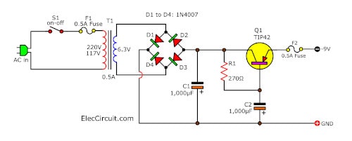
The input capacitor C2 keeps a stable voltage at the base of Q1. If the transistor has a lot of gains such a 50. It can reduce the rate of ripple to low down.
The transistor will increase a high current to the output at its emitter.
The output is full at 1A. Because of:
- a transformer is 1A to 2A, 6.3V SEC.
- And C1-1000uF 25V Electrolytic capacitor, you can change with 2200uF 25V, or add another one in parallel.
But this circuit also has ripple voltage and little noise. We have to improve it with Zener diode and transistor.
Working of the series voltage regulator
By the way, we come back to see in the circuit.
It is a simple series voltage regulator using a transistor and Zener diode. They produce an electronic filter. Because the load current passes through the series transistor Q1.
First, enter an unregulated DC supply to an input terminal. And the regulated output is across the load. The Zener diode gives a reference voltage.
And, the Zener diode keeps a relatively constant voltage at a base voltage of transistor Q1.
There are two interesting states:
- If the output voltage low down. Then, the base-emitter voltage rises. It causes transistor Q1 to conduct current more. So, the output voltage rises too. As a result, the output voltage is at a constant level.
- If the output voltage increases. Then, the base-emitter voltage decreases. It causes transistor Q1 to conduct less. So, the output voltage low down. Consequently, the output voltage is still at a constant level.
The advantage of this circuit. We can change a Zener diode current by a factor β or a gain rate of the transistor.
And, the effect of Zener impedance much reduce. So, the output has more stabilized.

Is it difficult? I do not want to see you like this.
Choosing the parts
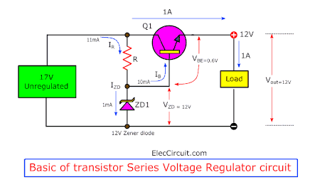
Watch in the simple Transistor Series Voltage Regulator again.
We will see that…
- R1 and ZD1 are a shunt regulator.—it is easy
- The load needs 12V power supply at 1A.
- ZD1 is a 12V Zener diode.—Because load requires 12V supply
- Why output is 11.4V? Q1 has a voltage drop of 0.6V from base to emitter.
So, if Zener voltage is 12V the output voltage will be Vout = VZD − VBE
12V – 0.6V = 11.4V - A transistor-Q1 passes 1A current to the load through collector-emitter. Some called NPN Emitter Follower form. We have to choose a transistor with an IC (collector current) more than 1A.
- We know that the Zener diode current should be low, about 1mA. And The resistor-R1 passes the current to it. Besides, R1 gives a base bias current to Q1.
- We read a datasheet. For example, TIP41, 2SC1061, etc. Q1 should have a gain of 100 times. So, a base current is 10mA. OR , 10mA x 100 = 1000mA = 1A . Thus the regulator will supply 1A to the load.
See in this power supply. We use a diode current only 10mA. But it can supply 1A load. Because the transistor amplifies the diode current by 100 times. So, It is more efficient than using just only one Zener diode.
We should do these.
- Choose a suitable value of the Zener diode.
- The transistor works well when the voltage across collector-emitter should drop at least 4-5 volts.
- Read more to improve the circuit with error voltage checker.
My father once said that if we did not understand. We must do it. It is true. I have many Transistor Series Voltage Regulator circuits below.
Series Regulator with adjustable output voltage
If we want a 15V power supply. What can we do?
First, In the previous circuit, we can change the Zener diode voltage is 15V. It is easy. But sometimes we cannot find it.
Second, use the 0-20V variable Power supply. It uses the same principle. Only adding more transistors and devices.
OR, try 2A Variable supply with overload protection. Please do not click it if you want a difficult circuit..Ha..ha…
These circuits, we can adjust the output voltage.
Also, we can modify the previous circuit to adjust the output voltage. It is good to learn.
Some called Series Feedback Voltage Regulator.
Watch in the circuit.
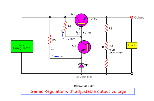
Of course, it has more devices. Of course, it has more devices. You do not worry. Slow and Slow learn with us.
First, The 20V input gets in the circuit. The R5 and ZD1 are a shunt regulator as above. It keeps 12V constant voltage at ZD1.
At the same time,
We called Q1 that a pass transistor. Because all the load current passes through it.
R4 passes the current to the base of Q2 with almost full input voltage to turn it on. Then, the power can flow collector to emitter. So, the output voltage rises.
Then, R1, R2, and R3 are a voltage divider network. They get the output voltage. Then, they produce a voltage at the base of Q2. The Q2 turns on.
Q2 will fully turn on the collector voltage is 12.7V. (Which is the Zener voltage plus the collector-emitter voltage drop) And, the output of Q1 is 12.1V. (Because of a base-emitter 0.6V drop).
We can adjust R2 to control the output voltage between 12.1V to 16V.
The transistor Q2 can power the output current from 0 to 1A. the same way as the previous circuit. But Q1 and a feedback resistor network help more regulation.
Check out these related articles, too:
How it works
It uses principles of negative feedback to keep the output voltage almost constant. It even changes the voltage and loads current.
Why can it do that? There are two interesting cases.
- First, Suppose the output voltage increases due to any reason. This causes more voltage across R2 and R1. Because it is a part of the output circuit. And, more voltage across base and ground of Q2 too. Q2 more works. Then most current flows R3. So, Q2 squeezed the collector-emitter voltage down. This causes the base voltage of Q1 reduces. And, Q1 runs down. Then, it can keep a constant output voltage. Because voltage is offset to lower.
- Second Similarly, if the output voltage tries to decrease. The feedback voltage or base-ground of Q2 also decreases. This reduces the current through Q2 and R4. This means more base voltage at Q1 and more output voltage. So, it can keep the output voltage at the original level.
Although it is now more effective than the past. But still, have more development. To reduce various disadvantages.
Download This
All full-size images of THIS POST as PDF in the Ebook. Thanks, support me. 🙂
And more…
What is more?
Keep Reading: Op-Amp Power supply Circuit works

I love electronics. I have been learning about them through creating simple electronic circuits or small projects. And now I am also having my children do the same. Nevertheless, I hope you found the experiences we shared on this site useful and fulfilling.

Es verdaderamente sorprendente la claridad conque transmiten el principio que persiguen en la enseñanza. Felicitaciones
Hello José Raúl Gamboa Alassio,
Thanks for your feedback. I am happy that you think it is useful. We will keep this working.
Thanks
Apichet