Imagine you finish the PWM signal with Arduino. You need to use a solenoid valve. But it uses high current to control. So you should use a solenoid coil driver circuit. This may be one good choice for you.
Which use two power MOSFETs, IRF150 as be an important component.
This can drive the Solinoid coil up to 8A load.
What is a solenoid coil?
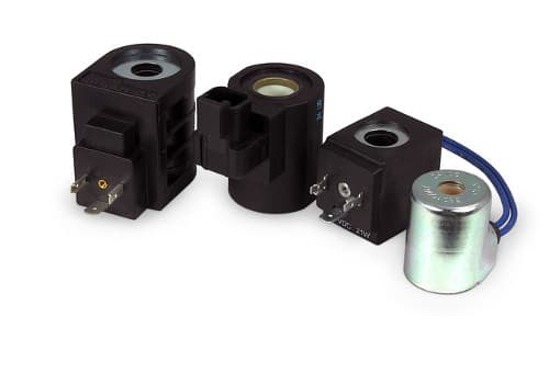
They are the electromechanical devices. We use an electric current to generate a magnetic field. To pull the iron and metal as we want. A relay is one of this type of device. They run as a switch by controlling electrical.
Also, we have an electric valve or called the solenoid valve. There is a mechanism which regulates the opening of fluid or air flows in a valve.
Recommended: How does an SCR work
Look in circuit
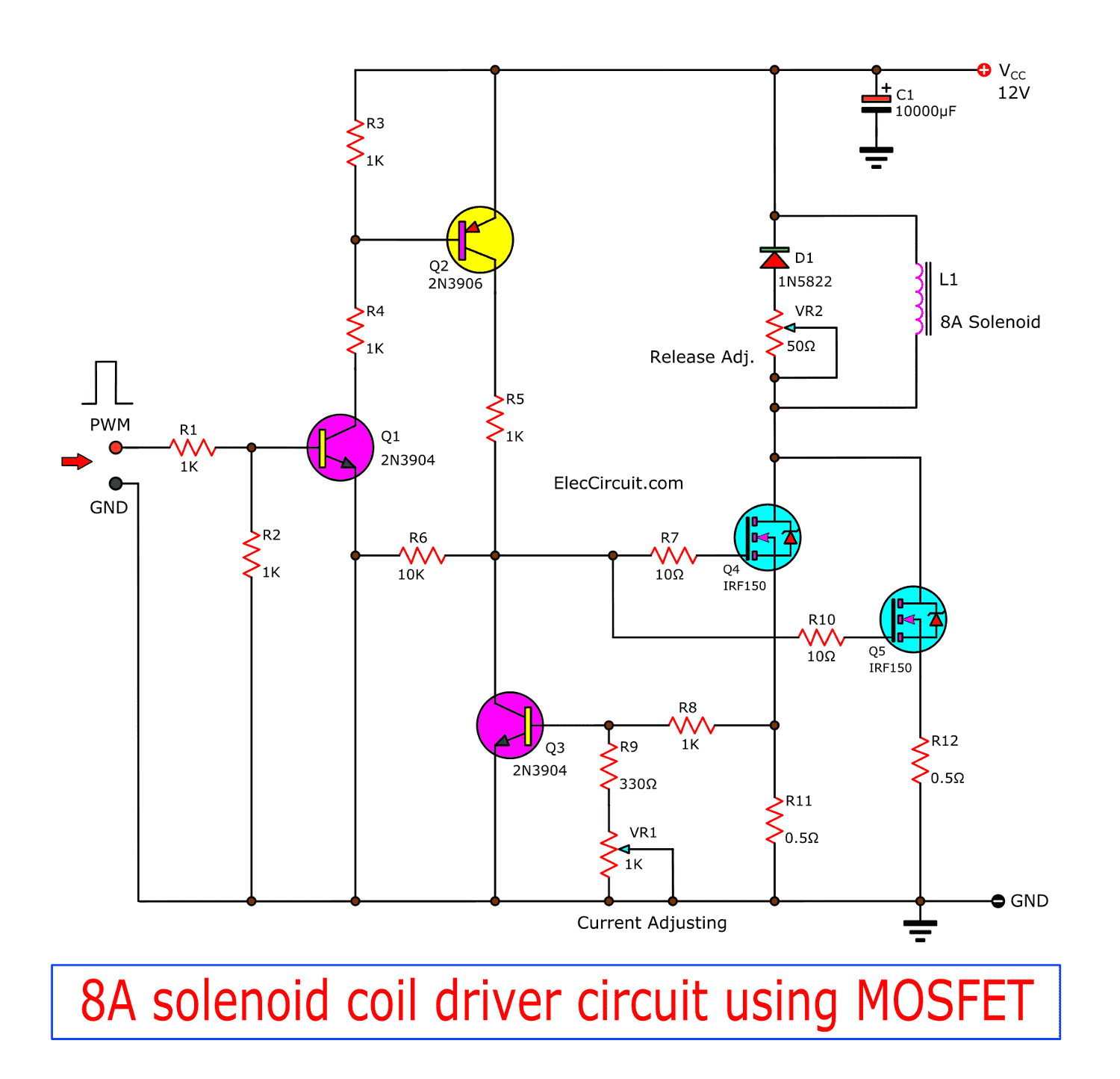
Why use MOSFET IRF150? It can drive high power load up to 38A max and resistance of it is 0.05 ohms only. However, In normal usage. We should connect them together in parallel. They will work well, extremely durable.
Why use MOSFET IRF150?
It can drive high power load up to 38A max and resistance of it is 0.05 ohms only. However, In normal usage. We should connect them together in parallel. They will work well, extremely durable.
The input is a PWM mode. It causes MOSFET runs with low current and not very hot.
Both Q1 and Q2 transistors increase the input signal to higher. Then the signal flows to G of both MOSFET. The full current flows the solenoid.
Then, R8, R9, VR1, and Q3 are the current adjusting section.
The D1- diode protects the current spike or high voltage turns back from the solenoid coil. And adjust VR2 to decorate Release Adj as well.
(PWM duty cycle) D = Vhigh / Vlow. If we want about 3V, D = 3/12 = 0.25 etc. If we want about 9V, D = 9/12 = 0.75.
We adjust VR1 depended upon a kind of solenoid. We can set get from 4A to 9A current.
Use The C1 increases the efficiency of the circuit.
The detail is other, please look at the circuit.
CR: Circuit design by aircraftdesigner.
Component lists
0.25W Resistors, tolerance: 5%
R1-R5, R8: 1K
R6: 10K
R7, R10: 10 ohms
R9: 330 ohms
R11, R12: 0.5 ohms 10W Resistors
VR1: 1K Pot
VR2: 50 ohms Pot
C1: 4700uF-10000uF 25V Electrolytic
Q1, Q3: 2N3904, 0.4A 40V NPN transistor
Q2: 2N3906, 0.4A 40V PNP transistor
Q4, Q5: IRF150, N-channel 100V 0.055Ω 38A MOSFET
D1: 1N5822, 3A 40V schottky diode.
Also, we recommend…
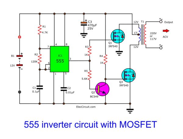
IC 555 inverter circuit using MOSFET
Here is ic 555 inverter circuit. is easy and small size. Because use NE555 and MOSFET as main. When use source is 12V battery will have output of 100 watts.[…]

24V DC motor controller with 20A Shot Circuit Protection
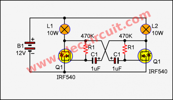
Simple 2 Lamp flasher circuit using MOSFET
I like a Simple 2 Lamp flasher circuit using MOSFET. Also, it is Astable Multivibrator. When you want a high power lamp flasher. This is a better choice for you. Why!
You may also like these:
GET UPDATE VIA EMAIL
I always try to make Electronics Learning Easy.
Related Posts


I love electronics. I have been learning about them through creating simple electronic circuits or small projects. And now I am also having my children do the same. Nevertheless, I hope you found the experiences we shared on this site useful and fulfilling.