Sometimes, our circuit requires a capacitor with a non-standard value (capacitance or voltage). In that case, using multiple capacitors in series or parallel may help.
However, capacitors in parallel and series have different electrical properties and nuances that can sometimes be confusing. So, how should we choose between them?
In this article, we will discuss joining multiple capacitors in series or parallel to form a capacitor circuit, as well as their electric properties and usage.
Parallel Circuit
Connecting capacitors in parallel circuits are often used in workloads that require high capacitance, such as power supplies and filter circuits. We will discuss many of its example usages later.
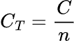
The total capacitance of this type of circuit is the sum of each individual capacitor’s capacitance, as shown in the following formula.
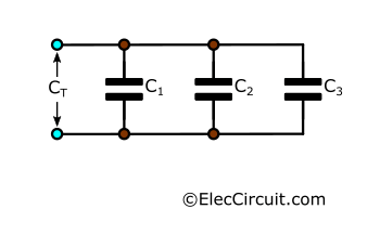
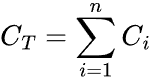
In other words,

If you recall, there are three factors that determine the capacitance of a capacitor: the area of the plates, the distance between said plates, and the dielectric material.
Connecting capacitors in parallel essentially combines the plates of capacitors in the circuit, resulting in a single capacitor whose plates have an area (AT) equal to the sum of the areas of plates (An) in the circuit.
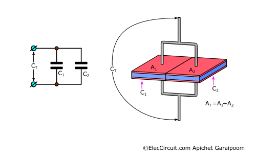
The larger a capacitor’s plate area, the more charges it can store, thus, the higher its capacitance. This is why parallel capacitor circuits have a higher combined capacitance than their parts.
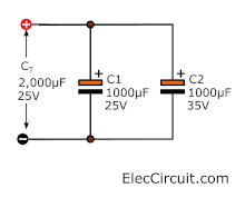
However, the capacitor with the lowest voltage rating will limit the voltage of the entire circuit. For example, in a two-capacitor parallel circuit comprising a (C1) 1000μF 25V and a (C2) 1000μF 35V capacitor, the circuit’s capacitance is 2000μF, the sum of C1 and C2, but the circuit’s voltage remains at 25V, C1’s voltage.
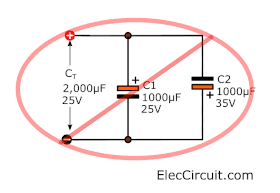
Caution: When connecting an electrolytic capacitor in a parallel circuit, pay close attention to the polarity. Connecting in the wrong polarity may damage the capacitor.
Increasing the Capacitances
To better understand the parallel capacitor circuit, let’s examine its practical usage in a 5V regulator circuit. A filter capacitor is an essential part of a regulator circuit since it reduces ripple voltage when the load draws too much power. In the example circuit below, a filter capacitor is calculated to be 3,600μF for a 1A load.
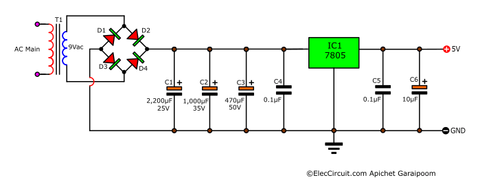
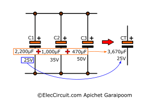
However, we do not have a capacitor with a capacitance close enough to that exact value. Thus, we use 3 capacitors—C1 2,200μF 25V, C2 2,200μF 35V, and C3 470μF 50V—in parallel instead.
All 3 combined have a capacitance of 3,670μF at a voltage of 25V. Normally, the 25V carried from C1 is rather problematic, but this circuit is only intended for 12.6V, so it is more than enough.
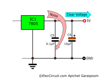
Noise Cleaner
We often add a small capacitor in parallel to the output of a power supply circuit to reduce voltage spikes or noises. Normally, the noises have a very high frequency, more than 1MHz. Here, the C5 capacitor acts as a ground for those noises to flow to, instead of flowing to the load. This is also known as a passive RC low-pass filter.
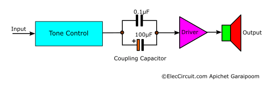
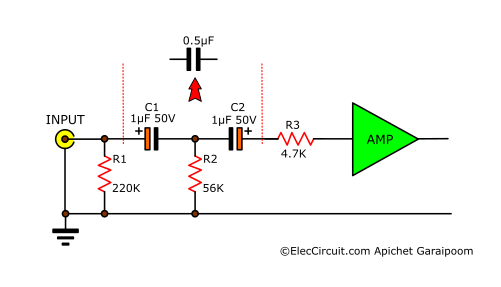
Coupling Capacitors
In AC circuits, a coupling capacitor usually connects two different circuits. This allows the AC signal to flow only from one circuit to the other while blocking the DC signal; this is also known as capacitive coupling or AC coupling.
In this example, the 100μF capacitor will have lower efficiency in blocking higher-frequency DC signals. Therefore, adding the 0.1μF capacitor in parallel helps increase the efficiency of blocking those higher-frequency signals.
Read also: Capacitor Time Constant
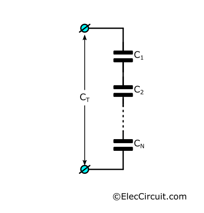
Series Circuit
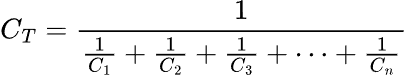
Connecting capacitors in series circuits is used when a higher capacitance matters less than the voltage. The total capacitance of a series circuit is the reciprocal (“one over” or ⅟) of the sum of the reciprocal of each capacitor’s capacitance. It is easier to understand in the form of a formula.
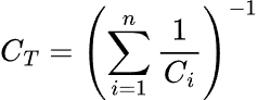
Or,
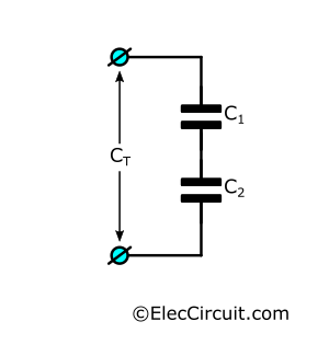
There are two other ways to calculate the capacitance; if only two capacitors are concerned, using the following formula is simpler.
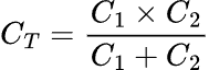
Furthermore, if all capacitors have the same capacitance, the following formula is also an option.

Where C is the common capacitance of all capacitors, and n is the number of capacitors in the circuit, for example, a series circuit with three 0.1μF capacitors will have a combined capacitance of:

In a series circuit, rather than the increased total plate area, the total distance between plates increases. We already know that the further the plates are apart, the fewer charges they can hold. And fewer charges mean less capacitance.
Therefore, the total capacitance of a series capacitor circuit is always less than its part because the distance between plates adds up.
However, the voltage of a series circuit is the sum of its components’ voltages, so a series capacitor circuit can have a very high combined voltage. In the above example, suppose that all three 0.1μF capacitors have a working voltage of 100V; the total voltage of the circuit will be 300V (3×100).
Now, we get to the example of the usage of series capacitor circuits.
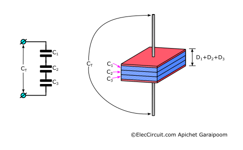
High Voltage Capacitor
Ionizing air molecules requires a very high negative voltage in applications such as air purifiers or ionizers. These devices are often configured with a high-voltage rectifier circuit that includes a high-voltage capacitor with a voltage of more than 7,000V.
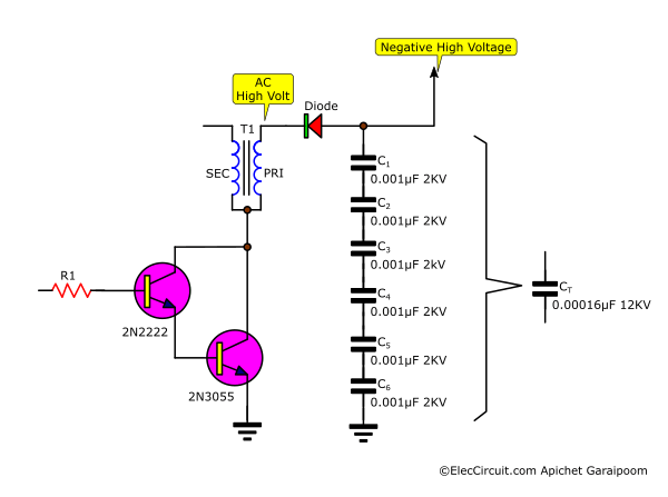
However, instead of a single very high-voltage capacitor, we would typically use several smaller capacitors. For example, to achieve 12000V, we can connect six 0.001μF 2000V in series. The result capacitor will have a voltage of 12000V and a capacitance of 0.00016μF (0.001μF divided by 6).
Converts Capacitor From Polarized To Non-polarized
It is sometimes possible to connect two electrolytic capacitors—which are polarized—in series. In this form, they function as a non-polarized capacitor. It has a wider frequency response compared to a single capacitor, which is why it is often found in a pre-amplifier circuit.
Conclusion
Is it better to connect capacitors in series or parallel? The answer is complicated and depends a lot on the workload requirements. Generally, if you need a very high-capacitance capacitor or want to decrease power supply noises, connecting capacitors in parallel is a better option. However, if you want to achieve a very high voltage in your circuit, connecting multiple capacitors in series is the way to go.

I love electronics. I have been learning about them through creating simple electronic circuits or small projects. And now I am also having my children do the same. Nevertheless, I hope you found the experiences we shared on this site useful and fulfilling.