It is easy if you control DC motor in a single direction. Sometimes you think. How to rotate DC motor in both directions. You are not worried. There are many ways to control speed, on-off, and dc motor reverses rotation.
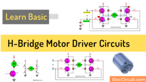
Read first: How does H-bridge motor driver works
In these circuits below use many types of components, power transistor, MOSFET and Relay.
The input of these circuits may be low volt of DC pulse, digital circuits, Arduino, and more.
2 channel DC motor driver on saving a model
This is 2 channel DC motor driver on saving the model. Using transistors as main components. They can control rotate direction and ON-OFF motor. So it is easy and cheap than MOSFET.
They have 2 input and if both inputs are “1” (12 volts). What will happen? If some input voltage is “0” (such as input A). The transistor Q5 will conduct a current, causes to transistors Q1 and Q4 also conducts.
Next, the DC motor is running in one direction. When it comes this time, we will explain what is part of this circuit that saving.
You will notice that. Each pair of transistors in the bridge. They control only one transistor driver. This thing not only saves equipment.
It also saves energy. Which is opposite to the two transistor driver. When the transistor Q5 (BD140 or BD136) conduct the Q1(BD242) work too. The current flows through Q1 by controlling of Q5.
The current goes to the base of Q4. It causes Q4 (BD241) also conduct. This means that we use the base current of Q1 and Q3(BD242).
In driving the Q4 and Q2(BD241), respectively. Which it makes we can drive the common motor circuits.
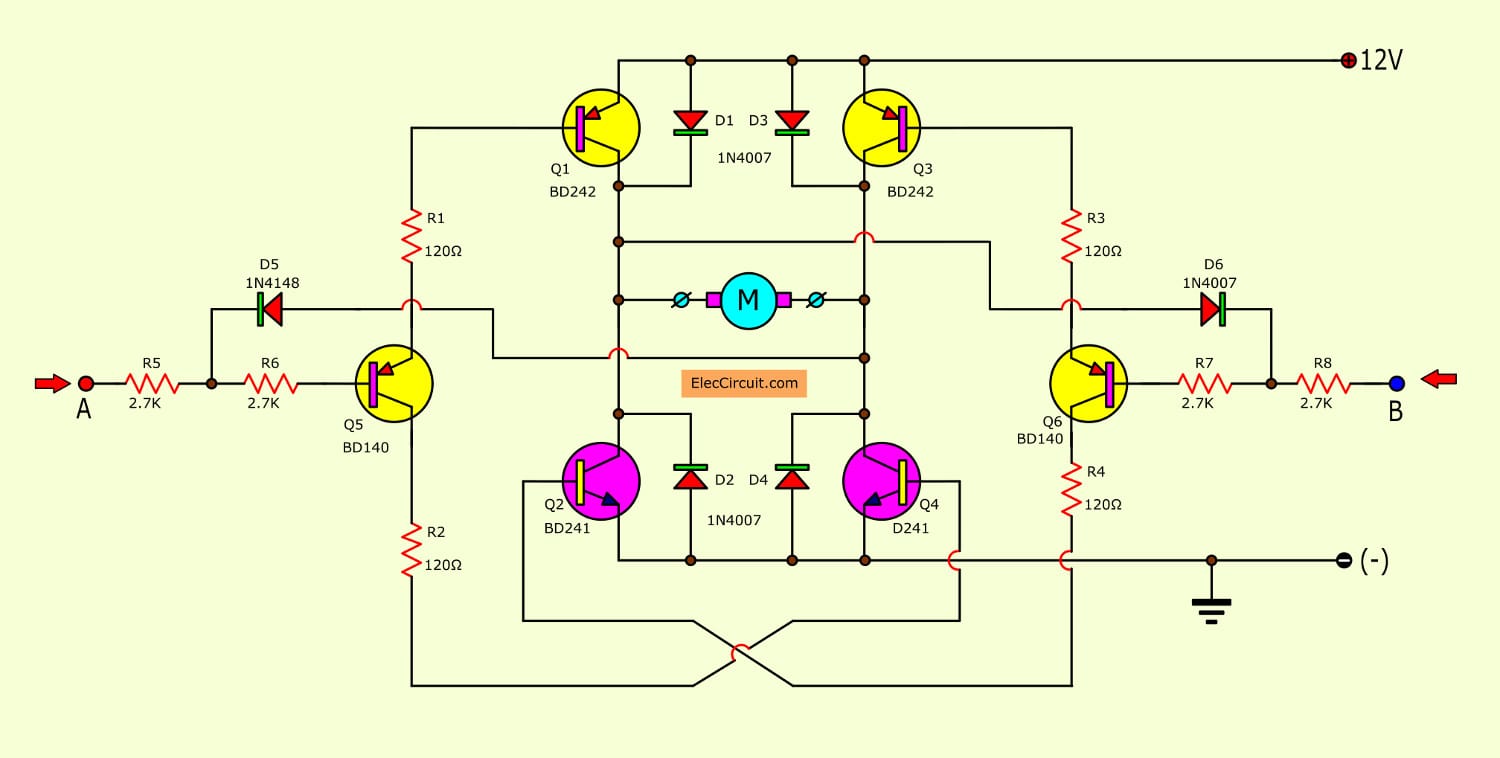
There are two other components that contribute, diode D5 and D6. Which it will protect the transistors and circuits do not damage. If both inputs are “0” at the same time.
For example, If input A has voltage is 0 volts, Q1 and Q4 will conduct both, and an anode of D6 will be connected to 12 volts.
If the input B is “0” with Q6 (Including Q2 and Q3) Will not be able to a conductor. Because the base leg of Q6(BD140 or BD136)is connected to the positive voltage. So input B will be triggered just continue on. After the voltage at A is “1” only, and conversely for the other one half.
We can use the pulse width modulation (PWM) of the speed control of DC motor. That is if the input signal at input A or B is a discrete signal.
The pulses can be wide, it can be used to control the speed of the motor. If the motor rotates quickly narrow pulses.
If you want to get the motor to work hard, maybe instead of Q1-Q4 with a Darlington, Which will flow rate is sufficiently high.
The input circuit of working at logic “0”. Therefore, it is suitable to drive a logic-level TTL. If the power supply for motors greater than 5V.
We must use the TTL gate that has an open collector output. The maximum current that motor will run is 1 amp and the current undisturbed is almost zero.
Recommended: How does an SCR work
DC Motor direction Controller
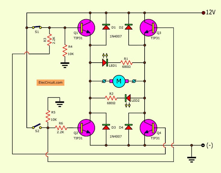
You can control the direction of the DC motor by two Switches. Both S1 and S2 are normally open, push to close, and press button switches. The diodes are Red or Green. They indicate a direction.
You may need to alter the TIP31 transistors depending on the motor being used. Remember, running under load draws more current.
This circuit operates a small motor for opening and closing a pair of curtains. As an advantage over automatic closing and opening systems, you have control of how much, or how little light to let into a room.
The four diodes surrounding the motor, are back EMF diodes.
They are suitable for the 12V motor that drawing 1A under load. You should use the 1N4001 diodes.
MCU Control Motor Speed and Direction
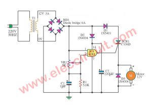
This is a powerful motor controller 12V circuit. With a signal, MCU Control is high-class voltage, about 3V. It can motor control turn advance or walk go backward all right. By use power mosfet number IRF150 use apply to 100W small stump size hills. The relay 12V 2 contract , for change electronic pole gives motor. By feed, a signal Reverse Rotation change B pins of 2N3904 give it works to give the electric current to the coil relay.
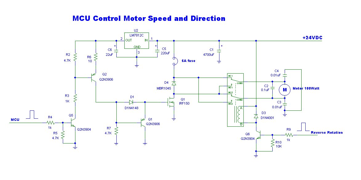
This circuit uses a voltage 12V at current about 10A. The C1-4700uF help increases the efficiency of the circuit. While feed the power gives motor during first. The D2 use protects the electric current pulls sharply from motor harm with MOSFET Q1-IRF150 get. Other detail in the circuit.
You may also like these:
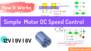
- Simple 12V | 9V | 6V Motor DC Speed Control with PWM mode
- 555 PWM LED dimmer circuit diagram | Power Battery Saving
- 8 simple touch switch circuit projects
GET UPDATE VIA EMAIL
I always try to make Electronics Learning Easy.
Related Posts

I love electronics. I have been learning about them through creating simple electronic circuits or small projects. And now I am also having my children do the same. Nevertheless, I hope you found the experiences we shared on this site useful and fulfilling.
wow u are the first
Thanks