Today I am going to show you this circuit. Do you want to control the speed of DC motor? We have many ways to do it. But if you want easy and cheap.
These are 12-volt DC variable-speed motor controller circuit using CMOS. They use the principle of PWM motor control mode. We can adjust the speed of 12V small motor. Even 6V or 9V Motor, this can be used, too.
It is easy and uses a few components that IC digital and transistor driver as main.
The motor speed control method
The voltage can control the speed of DC motor well.
Normally, low voltage causes the motor speed is low. But when high voltage causes the speed of the motor is high.
The idea of a good voltage change is the pulse. Look at the waveform below.
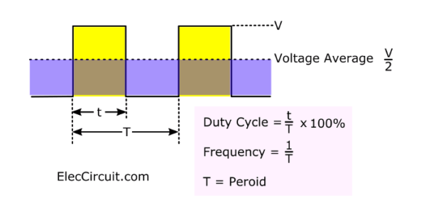
Imagine connecting to a lamp. Then its brightness drop. And, the voltage average is low half of the power supply voltage.
We have an important observation:
- T = Period
- Frequency = 1/T
- Duty Cycle = t/T x 100%
The average voltage will vary depending on:
- Frequency: the high-frequency pulse will receive the average voltage greater than a low-frequency pulse.
- Period: More importantly! When the Duty Cycle of Period is greater, it will get the average voltage more too.
Are you understand? I hope you clearly understand even my English is poor.
Suppose that: Voltage level is 10V, t = 0.2mS, T=1mS,
Duty Cycle =0.2mS/1mS x 100% = 20%
So, the average voltage is 0.2x10V = 2V
Recommended: SCR circuit diagram
Thus, we need an oscillating circuit to control the switch on-off the motor. And, it can be adjusted to the duty cycle.
There are many ways to do it. But gate digital is easy and cheap.
We used to use the Digital gate as an oscillator in LED blinking.
And, we use a not gate from connecting of 4011.
Also, we can use the NOR gate to NOT gate.
Recommended: Simple IC-4011 LED flasher circuits
Look at the image below.
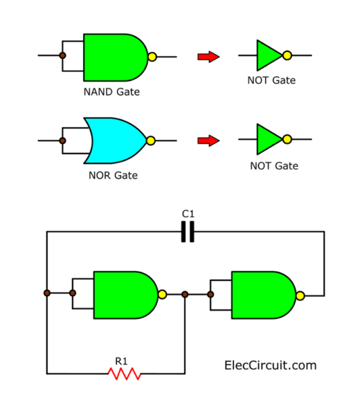
Basic oscillator using NOT gate from NAND or NOR gate.
Related: 4011 Tone Generator circuit projects
But we still have another interesting issue. When we need the maximum speed, we have to adjust the duty cycle to 100%.
Of course, we are not able to find a normal switch that works fast at that level. How to do it? Use a transistor is best. It is easy and cheap, too.
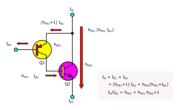
Look at the basic Darlington transistor. They can drive a motor 12V at 1A current.
We have 2 circuits diagram to show you.
The advantage of these 2 circuits is that if you have a 9V or 6V motor or battery, you can use it immediately. Because we use a CMOS IC that can be used with a voltage of 3V to 15V.
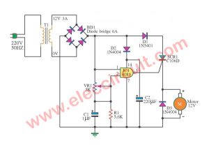
First: 4011 Motor DC Speed Control
If you want to control the speed of a small 12V DC motor. Before will see others circuit. I introduce this circuit as the figure that shows below.
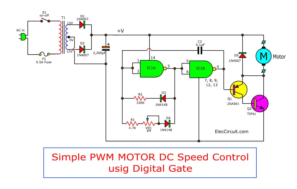
It is a simple circuit. Because it uses the 4011 NAND gate CMOS as the main part and a few other components.
Which it is determined to works in the PWM model (pulse width modulation) so has high It is highly effective, Low power consumption.
Interesting Thing
- We use a potentiometer-VR1 to adjust the speed as needed.
- Next, we use two transistors are TIP41 and BC548 to connect in a Darlington makes drive current higher.
- We should hold a heat sink at TIP41 due to its heat when they are applied.
- While motor function, maybe a reverse current, it must put Diode D1-1N4148 to prevent this circuit.
How it works
Let me explain why it works. Here is the step-by-step process.
- The AC main comes to this circuit to a power supply section. They include T1, D1, D2, and C1.
- T1 converts a main 220V voltage down into 12V.
- Then, AC voltage current flows through to D1-D4 to the full-wave rectifier into DC current.
- And, there is a C1 filter to DC voltage that smooth so well.
- This circuit is a full-wave rectifier that center tap transformer and 2 diodes.
- Also, you can use a bridge rectifier without a center tap transformer and 4 diodes.
This current is divided into 2 parts.
- To motor: It almost all flows.
- To 4011 CMOS: generate a square wave pulse. This IC includes 4 NAND gate. But we use just only 2 gates. Each will be set to the inverter gates and connected to the pulse oscillator.
Duty Cycle and oscillation adjusting
If we use the only resistor like a basic circuit. The duty cycle is only 50% and is not customizable.
We use 2 resistors. The first one is adjustable. And, both diodes D3 and D4 determine the direction of charge and discharge current of C2.
It makes it possible to adjust the duty cycle unequally. R2 determines the time for the output range to be 1.
Both R1 and VR1 will set the time of the output range to be 0.
Adjusting VR1 will change the duty cycle of pulse.
When the VR1 is adjusted to the lowest setting, it will cause the duty cycle to reach 100%. The motor speed will be the highest.
But when the VR1 is high, the square signal width is low (Leaving more space). Or the duty cycle will be lower.
Darlington transistor Driver
Since the output of CMOS cannot drive the motor directly. Because its current is too small.
So we use a transistor to drive the current. Using two transistors connected in a Darington pattern, it has a very high current gain. That is to say
IO/IB1 = hFE1 = hFE1 hFE2 and
IC2/IB1 = hFE1 hFE2
The transistor Q2 will pass the current directly. The choice of Q2 must correspond to the current of the motor as well. Do not forget that the starting motor current is several times of no-load current.
Normally, transistors that endure the high current. They have a low current gain (hFE or B). Therefore, hFE1 is usually greater than hFE2.
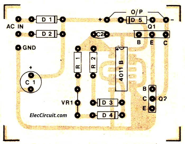
How to build
Do you want to build it? This circuit is a few parts. So, you can build it on a universal PCB. Some, want to make a better project. Look at below! It is a copper PCB layout and a Component layout.
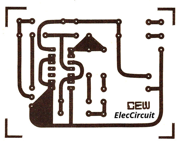
In other detail, in my view you are smart. You have some skills to do about Electronics.
The parts list
The resistors 1/4W +-5%
R1: 4.7K
R2: 330K
VR1: Variable resistors 2M(B)
The capacitors
C1: 0.1uF Ceramic type
The semiconductor components
IC1: CD4011, Quad 2-Input NAND Buffered B Series Gate
Q1: 2SA561, 0.15A 50V PNP transistor
Q2: TIP41, 4A 40V NPN transistor
D1, D2, D5: 1A 1,000V Diode, 1N4007
D3, D4: 0.75A 200V Diode, 1N4148
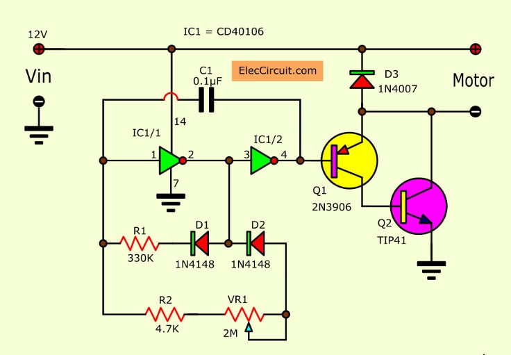
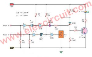
Second: Not gate Pulse width modulation motor control
This is the Pulse width modulation of motor control using CD40106. Usual, we just enter the voltage and DC current source to the DC motor, Makes motor can be rotated.
If will modify or regulate the speed in the rotation of the motor.
We will need to enter the voltage look into pulses or periodically. Which will make the average voltage at the output is different.
By the pulse, voltage is high frequency will have the average voltage than the low-frequency pulse.
The same with the pulse has over duty cycle value, it will have the average pressure much than low duty cycle value.
How is CD40106 Pulse width modulation motor control
The average voltage will be supplied to the DC motor. To control the motor rotation is slow or fast.
This circuit uses the above principle. By making the pulse generator circuit or astable multivibrator.
Which they consist of IC1 / 1 and IC1 / 2 inverter gate with C1, R1, R2, VR1 and diode D1, D2.
The signal generator has the duty cycle value that can adjustable or can rotate with VR1 there.
The pulse signal of the circuit. When it is adjusted to get the duty cycle too much there is a maximum of 100%.(signal has the most positive pulse.) Makes the motor it will spin the fastest.
If the percentage of the duty cycle reduced, the speed will reduce as well.
The pulse output signal from IC1/2 will enter to Q1(2N3906), Q2(TIP41) that are connected to the Darlington amplifier circuit. To extend the current pulse up.
Then, drive the motor, connected to the output terminals of the circuit.
The Q2(TIP41) acts through a direct current to the motor. The selection will need to look in accordance with the current use of the motor.
I choose to be more current, because when the motor starts to draw more the current from the power supply than the normal rotation. Or not the motor is loaded.
This circuit is suitable for the DC motor with a power that is not much. It is small enough that the voltage and current not exceeding 12 volts 2 amps.
Which reduces power loss to the motor and the circuits.
The parts list
The resistors 1/4W +-5%
R1: 330KΩ
R2: 4.7KΩ
VR1: Variable resistors 2MΩ
The capacitors
C1: 0.1μF Ceramic type
The semiconductor components
IC1: CD40106, CMOS Hex Schmitt Triggers
Q1: 2N3906- PNP transistor
Q2: TIP41- 4A 40V NPN transistor
D1, D2: 0.75A 200V Diode, 1N4148
D3: 1A 1000V Diode, 1N4007
This circuit requires enough power supply. Do you have this one? If you do not have it. Look:Learn Many Power supply circuits
Stops problems about components and The project not work.
Although the circuits are is not the same.
It can control speed motor with PWM as well.
You may also like these:
- DC motor controller diagram using SCR and CMOS
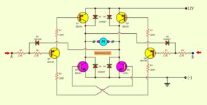
- How to rotate dc motor in both direction | 3 Circuit ideas
- 555 PWM LED dimmer circuit diagram
CR: Motor photo by SWHstore
But if you want circuit that a good than this circuit. see these circuits.
PWM Control Speed 12V Motor for power dc motor of 12V to 24V motor using TL494.

I love electronics. I have been learning about them through creating simple electronic circuits or small projects. And now I am also having my children do the same. Nevertheless, I hope you found the experiences we shared on this site useful and fulfilling.

Diode D3: What does it mean 1000MF?
Hi, @nikolic
I truly regret for my error.
Now I modify it. please see it again.
The language used for the text under various schematics is not quite understandable at places and meaning is lost. I have fullest regards for your mother tongue but can something be done about my problem. Your website is so informative and rich in technical material that I possibly cannot ignore it. Your efforts are commendable. Keep it up.
The Q1 is BC548 or BC549 ,and u means ( While motor function, may be a reverse current, it must put Diode D1-1N4148 to prevent this circuit.)
so this is the D1 or D5???
Sir, by this method (pwm) , can be speed control of stepper motor.,,
what is the purpose of the two resistor sir? and why itis a Npn Bjt and not pnp? pardon may ignorance because I will have a report and I will use this circuit so that is why I Need to report perfectly and answer all question that may teacher prepared if I want to pass…
Have you got a controller that can run a small motor from 24vAC to 24V DC max 12 amps 10 amps will do
Ian
i tried this circuit and it fried the TIP41 transistor , am not sure what i got wrong