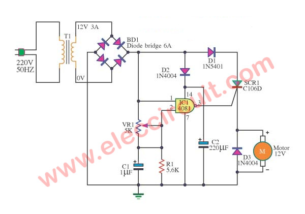
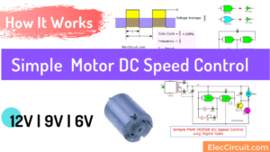
This is a speed motor controller circuit of a 12V DC motor. as SCR DC motor speed control circuit using IC-CMOS. You can adjust the speed of rotation of the spindle motor from 5 to 60 cycles per minute.
How does it work
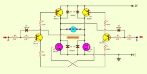
To begin with, the 12V AC voltage from the Secondary transformer comes to bridge diode-BD1. It rectifies from AC (Alternating Current) to DC (pulsed DC).
SCR DC motor speed control circuit using IC-CMOS
This can use for DC motor and SCR1—The SCR needs to use DC to A-K lead—. Which uses just the pulsed DC only.
But we also use digital IC.
Cr: Photo Power SCR Bridgold
Second, we use one NAND gate CMOS-IC, CD4081. It requests a stable power supply to pin 14. The D2 gets the pulsed DC to filter to smooth DC current with C2-220uF.
Pin 1 gets the pulsed DC directly. And the other into pin 2. Next, The VR1, C1, and R1 are the phase shift circuit to delay the pulse DC to slow down.
After that, the pulsed DC from pin 3 to triggers the gate of SCR1 to turn on.
The working of SCR like switches on-off the pulsed DC to the motor, makes it rotate. The Speed of the motor can adjust by VR1.
If pulsed DC has a “high” state more than a “low” state. It makes more current to the DC motor, it rotates very fast.
But in the opposite way, the “high” is less than the “low” state. It rotates too slowly.
The D1 prevents the noise from the motor.
The D3 is reverse-voltage protection of motors. This can cause circuit damage.
If the circuit uses the high power motor. You need to install a large heat sink to BD1, D1, and SCR1. Because they are very hot, may damage.
Read: 12V DC Motor Speed Controller using 4011
How to builds
This project is easy because uses a few parts. For faster building, if we assemble these circuits in the Universal PCB Figure 2 is the components layout for a guide.
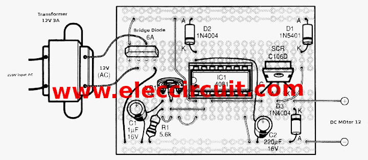
Figure 2 the components layout of the DC motor controller diagram with SCR and CMOS IC.
Learn more: SCR circuit diagram
The components lists.
IC1: CD4081, CMOS Nand gate IC
SCR1: SCR-C106D or equivalent
BD1: Bridge Diode 6A 200V
D1: 1N5401, 3A 100V diode
D2, D3: 1N4004, 1A 400V Diode.
T1: Transformer 3A 12V
C1: 1uF 16V Electrolytic capacitors
C2: 220uF 16V Electrolytic capacitors
VR1: 5K potentiometer
R1: 5.6K, 0.25W resistors
PWM DC motor controller with NE555 »

I love electronics. I have been learning about them through creating simple electronic circuits or small projects. And now I am also having my children do the same. Nevertheless, I hope you found the experiences we shared on this site useful and fulfilling.

Hello
I need a 12v 5A dc motor controllers please help me?!
projert report DC motor controller diagram with SCR and cmos ic
projert report DC motor controller diagram with SCR
in DC MOTOR CONTROLLER DIAGRAM WITH SCR AND CMOS IC what would be the capacitor value for both capacitor.please give the reply as soon as possible.
i need a circuit diagram of DC motor with trnsformer, regulator, diods, rectifier.
The output of the NAND is only two states – logic 0 or logic 1, how will this allow a continuous variation?
Because by adjusting the potentiometer, we can only have output of NAND (Thyristor gate signal) as high or low.
the secret is on half wave rectification ,when goes high charge c1 when goes low discharge c1 like zero crossing regards
this circuit is working and good one>< thanks
Hi muhammad ali,
Thanks for your feedback.
how the ic controls the speed of the motor please sir explain
this circuit is working good thank you admin of this post
Hi gopinath.
Thanks for your feedback.
pleas tell me how much current rating of 12v dc motor use in DC motor controller with SCR and cmos ic
please let me know 48 dc.v forklift motor speed control SCR control system
Thinks
give me every detail of all the components used in this model
how the ic controls the speed of the motor please explain..
and also current rating of dc motor….
Hi,Faneshwar Patel
Thanks for your feedback.
DC motor is about 12V 2A. or 30-50watts.
frnd mene ckt ko sahi design kiya pr motor nahi gumi
pls guide me
sir i want control a dc motor in four quardints
plz explain and guidme
very well
this website is very usful for engineering student and also like me
hello sir i need a pcb layout of speed control of dc motor by using scr or cmos ic
pls send me its layout
THANX®ARDS
md ahshan ali
Hi md ali,
Thanks for your feedback.
I need a 10HP motor for speed control
Pls explain the work of IC in above circuit.
I have designed circuit as per given circuit diagram;but it is not working…
The variation in potentiometer is not controlling speed of dc motor….
Please help me with the feedback asap, it’s urgent please
sir plz tel me the speed control of 12v 5a dc motor is compulary required heat sinks kadha ela connect cheyali circuits lo and rating of heat sink entha
could you please send me the PCB lay out of this circuit…..i really need this for my semester project
Hi
thank you for the above circuit.
can the circuit be up scalled to carry high voltages and current; say 250 dc at 100 A?
Can any one say the application,merits and demerits of this circuit….
THIS CAN BE USED TO DO YOUR HOUSEHOLD WORKS
Hi VISHNU,
Thanks for your feedback. Yes, you can use it in your house.
please how can I improve this project of this motor speed control using CMOS NAND