We often use a Zener diode in all kinds of electronic circuits, such as power supplies, voltage detectors, and many others. It certainly is an incredibly useful component, but do you understand it well enough?
In this article, we will learn how a Zener diode works, its operating principle, and some of its example applications. Let’s get started!
Recommended: For beginners should Learn Electronics.
What is a Zener diode
A Zener diode is a special form of semiconductor diode. Like a normal diode, it is a two-lead device with defined polarity—anode (A) and cathode (K)—but its working principle differs significantly from that of a normal diode, which we will discuss later.
The image below shows an actual Zener diode (left) alongside its circuit diagram symbol (right).
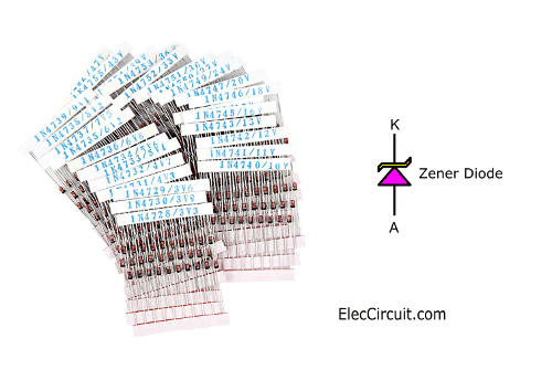
A Zener diode comes in many sizes depending on its wattage. A larger one means higher wattage; for scale, the picture above is only half a watt (0.5W). Credit Photo Zener by TeOhk
Basics of How a Zener Diode Works
The basics of how a Zener diode works are not complicated, but to make it easier to grasp, let’s start by comparing it to another closely related electronic component: a diode. If you recall, a diode conducts electrical current in one direction but not the other, a sort of one-way road for current. This is also true for Zener diodes.
To be more precise, a normal diode offers very little resistance to current flowing from its anode (A) to its cathode (K); in other words, its forward bias. Likewise, a Zener diode functions in the same manner, allowing current to flow from its anode (A) to its cathode (K) without hindrance.
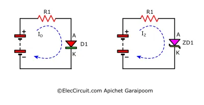
However, as we already know, currents flowing in the opposite direction through a diode—from its cathode (K) to its anode (A)—will be met with a very high resistance, effectively preventing them from flowing through. This is known as the diode’s reverse bias. A Zener diode also possesses this function but uses it differently, as we will see later.
Forward Bias and Reverse Bias
To better understand how a Zener diode functions in both forward and reverse bias, let’s look at the following circuit analysis of a 3V Zener diode. In this hypothetical circuit, apart from the Zener diode, there is also a resistor. Both components are in series with each other and are being powered by a 6V power source.
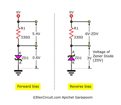
In the forward bias, positive current from resistor R1 flows through the Zener diode. Here, the Zener diode functions like a normal diode, allowing current to flow without much restriction.
The voltage across the Zener diode is about the same as its turn-on voltage, 0.6V, whereas the rest of the voltage is on the resistor. The combined voltages from both the Zener diode and the resistor are equal to the supply voltage.
In the reverse bias, the Zener diode would, in a way, function similarly to a normal diode. Here, the Zener diode does not allow current to flow through when the voltage across it is lower than the breakdown voltage.
However, when the voltage exceeds the breakdown voltage, the Zener diode will conduct current. And now, the voltage across it will be the same as the breakdown voltage, 3V; the rest of the voltage will be on the resistor.
Breakdown Voltage
As seen above, in a reverse bias, a Zener diode operates by using the breakdown voltage, which allows current to flow through it when a reverse voltage reaches the breakdown point, also known as the Zener voltage.
The breakdown process in a normal diode can cause damage to the diode, whereas a Zener diode commonly has a lower breakdown voltage. As a result, the breakdown process in a Zener diode is controlled and does not cause damage to itself. For example, a typical diode has a breakdown voltage of 50V, whereas a Zener diode usually has a much lower breakdown voltage of around 5V.
The I/V graph below shows the relationship between the current and voltage of a Zener diode.

In the forward bias, current can flow through the Zener diode freely. The current begins to drop sharply when the voltage decreases below the Zener diode working voltage or turn-on voltage, in this case 0.6V.
In the reverse bias, initially there are only very tiny amounts of current flowing through the Zener diode. This current is known as leakage current; it is negligible and usually does not affect circuits. The line graph continues to hold this position until the voltage goes above the breakdown voltage, at which point the current suddenly and significantly increases.
It should be noted that the voltage across the Zener diode remains nearly at the breakdown voltage level throughout the breakdown process. Consequently, a Zener diode can be used to maintain a constant voltage for reference and other purposes.
Zener Diode Practical Comparison
To better understand how a Zener diode works in reverse bias, let’s look at this simplified practical comparison to a weir or dam. In this scenario, we suppose that the height of the water measured from the ground corresponds to the voltage in a circuit, and the volume of water flowing reflects the current flowing through the circuit.
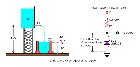
In the image above, the circuit on the right has a constant output voltage of 3V, with the ability to vary Vin from around 8V to 15V, but we normally use 12V, so no matter how much Vin changes, Vout will still be at a constant 3V. This is the simplest regulator circuit.
Let’s compare it to a water flow and level system, assuming that the elevated water tank is the power supply (Vin), and the level at which the water flows out of it is the power supply voltage. R1 limits the amount of water flowing out from the tank; in other words, it limits the current from Vin.
The container beneath the tank represents the Zener diode; it has a hole drilled in its side at exactly ‘3V’ off from the ground.
The level of water released will remain constant at 3V no matter how high we increase the Vin level.
If the water does reach the hole on the side, the height of the water flowing out is guaranteed to be ‘3V,’ the same as the height of the hole.
Zener Diode That I Often Use
Once we know the desired voltage level, we can select the Zener diode corresponding to or of a similar voltage level and the appropriate wattage for our uses.
The higher-wattage Zener diode can be a substitute for the lower-wattage one. But the lower one should not be used instead of the higher one. Because in a circuit with a high current, the Zener diode will generate high heat and can be damaged.
I have collected many Zener diodes over the years, but there are many more that I have heard of but never used myself. So, the list below would only consist of the Zener diodes I have used often.
3V ZD (Zener Diode)
If we want a 3V Zener diode, we can use 1N5225 or BZX55C3V0 with the same 3V at 0.5 watts, but if you want higher wattage, use 1N4728 (3.3V at 1 watt) instead. This is the Zener diode that provides the closest voltage to 3 volts.
5V ZD (Zener Diode)
We would use the 5.1V Zener diodes instead, because the 5.0V ones are no longer available. The ones I often use are: BZX55C5V1 and 1N5231B.
Other Zener diodes with Voltage list
- BZX55C2V0 (2V)
- BZX55C2V2 (2.2V)
- BZX55C2V4 (2.4V)
- BZX55C2V7 (2.7V)
- BZX55C3V0 (3V)
- BZX55C3V3 (3.3V)
- BZX55C3V6 (3.6V)
- BZX55C3V9 (3.9V)
- BZX55C4V3 (4.3V)
- BZX55C4V7 (4.7V)
- BZX55C5V1 (5.1V)
- BZX55C5V6 (5.6V)
- BZX55C6V2 (6.2V)
- BZX55C6V8 (6.8V)
- BZX55C7V5 (7.5V)
- BZX55C8V2 (8.2V)
- BZX55C9V1 (9.1V)
- BZX55C10 (10V)
- BZX55C11 (11V)
- BZX55C12 (12V)
- BZX55C13 (13V)
- BZX55C15 (15V)
- BZX55C16 (16V)
- BZX55C18 (18V)
- BZX55C20 (20V)
- BZX55C22 (22V)
- BZX55C24 (24V)
- BZX55C27 (27V)
- BZX55C30 (30V)
- BZX55C33 (33V)
- BZX55C36 (36V)
- BZX55C39 (39V)
- BZX55C43 (43V)
- BZX55C47 (47V)
500mW Zener Diode (Nominal Zener Voltage)
- 1N5221B (2.4V)
- 1N5222B (2.5V)
- 1N5223B (2.7V)
- 1N5224B (2.8V)
- 1N5225B (3.0V)
- 1N5226B (3.3V)
- 1N5227B (3.6V)
- 1N5228B (3.9V)
- 1N5229B (4.3V)
- 1N5230B (4.7V)
- 1N5231B (5.1V)
- 1N5232B (5.6V)
- 1N5233B (6.0V)
- 1N5234B (6.2V)
- 1N5235B (6.8V)
- 1N5236B (7.5V)
- 1N5237B (8.2V)
- 1N5238B (8.7V)
- 1N5239B (9.1V)
- 1N5240B (10V)
- 1N5241B (11V)
- 1N5242B (12V)
- 1N5243B (13V)
- 1N5244B (14V)
- 1N5245B (15V)
- 1N5246B (16V)
- 1N5247B (17V)
- 1N5248B (18V)
- 1N5249B (19V)
- 1N5250B (20V)
- 1N5251B (22V)
- 1N5252B (24V)
- 1N5253B (25V)
- 1N5254B (27V)
- 1N5255B (28V)
- 1N5256B (30V)
- 1N5257B (33V)
- 1N5258B (36V)
- 1N5259B (39V)
1W Zener Diode (Nominal Zener Voltage)
- 1N4728A (3.3V)
- 1N4729A (3.6V)
- 1N4730A (3.9V)
- 1N4731A (4.3V)
- 1N4732A (4.7V)
- 1N4733A (5.1V)
- 1N4734A (5.6V)
- 1N4735A (6.2V)
- 1N4736A (6.8V)
- 1N4737A (7.5V)
- 1N4738A (8.2V)
- 1N4739A (9.1V)
- 1N4740A (10V)
- 1N4741A (11V)
- 1N4742A (12V)
- 1N4743A (13V)
- 1N4744A (15V)
- 1N4745A (16V)
- 1N4746A (18V)
- 1N4747A (20V)
- 1N4748A (22V)
- 1N4749A (24V)
- 1N4750A (27V)
- 1N4751A (30V)
- 1N4752A (33V)
- 1N4753A (36V)
- 1N4754A (39V)
- 1N4755A (43V)
- 1N4756A (47V)
- 1N4757A (51V)
- 1N4758A (56V)
- 1N4759A (62V)
- 1N4760A (68V)
- 1N4761A (75V)
- 1N4762A (82V)
- 1N4763A (91V)
- 1N4764A (100V)
Example Usages of a Zener Diode
Here are two common usages of a Zener diode: a voltage regulator and a voltage detector. We will go over the voltage regulator first and then move on to the voltage detector/indicator later. There are also a couple of example circuits for each usage.
Using a Zener Diode as a Voltage Regulator
The basic Zener diode circuit below is a low-current regulator circuit. The output current is determined by resistor R1, whereas the output voltage is equal to the Zener diode voltage at all times.
We can calculate the appropriate resistance of R1 using the formula:
R1 = (Vin – Vz)/(IL + Iz)
Normally, the current of the Zener diode, Iz, is about 5mA when connected to loads. Thus, we can substitute it for Iz, resulting in the following formula.
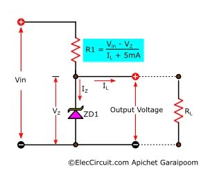
R1 = (Vin – Vz)/(IL + 5mA)
In conclusion, the load current determines the resistance of R1. Furthermore, the load current will pass through the Zener diode if no load is connected to the circuit. So, we have to offset the Zener diode’s current when calculating its wattage so that it can withstand the load current as well.
Choosing Zener Diode Wattage
Calculating the wattage of a Zener diode is as follows: The wattage of the Zener Diode (P) is equal to the Zener diode voltage (Vz) times the current passing through the Zener diode (Iz).
P = Vz x Iz
Note: Iz is obtained from the voltage across the resistor divided by the resistance of that resistor (R).
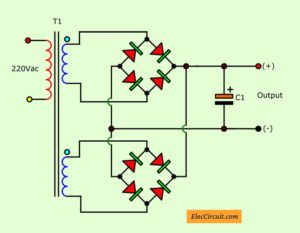
9V DC Voltage Regulator Circuit
This is a very simple AC-to-DC 9V regulator circuit that can output current less than 50mA. This circuit uses the same principle we talked about above. The DC voltage right after the full-wave diode rectifier is 16.8V, but at the output, the voltage drops to a constant 9V, which is the Zener voltage.
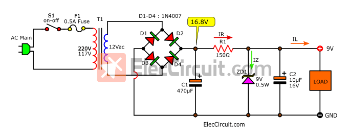
However, the main downside of this circuit is that it has a low output current of 50mA, which we will attempt to solve with the next circuit.
Read more about this particular circuit: 9V regulated power supply circuit diagram
Basic High Current Regulator Using Zener and Transistor
This circuit is quite similar to the previous circuit, but with the addition of a transistor. Because of the transistor, this circuit can supply much more current since the current can now flow through the transistor instead.
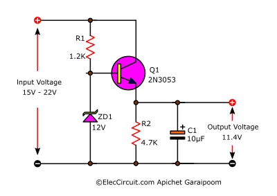
The Zener diode now provides bias voltage for the transistor. However, the output voltage would still be 0.6V less than the Zener voltage. This is because the voltage across B-E of the transistor is 0.6V.
Since the load current is now flowing through the transistor, it is dependent on the capability of the transistor. As a result, using a transistor with a higher current rating ensures that the circuit can also supply a higher current.
Parts list
- Q1: 2N3053, 0.7A 40V NPN Transistor
- ZD1: 12V 0.5W Zener Diode
- C1: 10uF 16V Electrolytic Capacitor
- R1: 1.2K 0.25W 5% Resistor
- R2: 4.7K 0.25W 5% Resistor
You may notice that the output voltage is not exactly 12V; instead, it is 11.4V. Which can be problematic if the load requires exactly 12V. The solution to the problem is to make the output voltage the same as the Zener voltage. So to achieve that, we can add an additional diode in series with the Zener diode, as seen below.
By adding this rectifier diode, the voltage across the diode will offset the voltage across the transistor’s B-E. As a result, the output voltage is now equal to the Zener voltage of 12V.
3V DC Regulator Using Zener Diode and Transistor
Let’s look at another voltage regulator circuit; this time, it is a 3V DC regulator using a Zener diode and transistor that can supply a current of 0.8A.
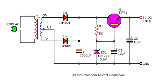
After the transformer reduces the voltage to 9V AC, it will go into the full-wave rectifier diodes D1 and D2, resulting in 12.6V DC at the other end. Subsequently, it gets filtered by C1 to make a smooth DC current, then passes through to the Zener diode, which will keep the output voltage constant.
In this circuit, we use 1N5227 or BZX55C3V6 for our Zener diode; they have a Zener voltage (VZ) of 3.6V. This is because the voltage across B-E of the transistor is about 0.6V. Therefore, using a 3.6V Zener diode ensures that the output voltage will be 3V exactly.
Lastly, C2 is a filter capacitor to maintain the Zener voltage stability when sudden current pulls, and C3 is also a filter capacitor to decrease the ripple voltage.
Parts list
- Q1: TIP41, 4A 40V NPN transistor
- ZD1: 3.6V 0.5W Zener diode ,1N5227 or BZX55C3V6
- D1,D2: 1N4001, 1A 50V Diode
- R1: 5K 0.25W 5% Resistor
- C1: 1,000uF 16V Electrolytic Capacitors
- C2, C3: 10uF 16V Electrolytic Capacitor
- T1: 117V/230V AC primary to 9V-0-9V,1A secondary transformer
What is more?
Zener Diode Voltage Regulator With Comparator OP-AMP
Now let’s look at this other interesting voltage regulator circuit that uses a Zener diode. This circuit will have much greater output quality because of the addition of a comparator OP-AMP.
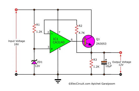
After receiving power, the voltage across the Zener diode will be at its Zener voltage, which is 12V, meaning that the voltage at pin 3 of the OP-AMP (CA3140) is also 12V.
This causes the output (pin 6) of the OP-AMP to have a positive voltage and bias the transistor Q1. Allowing current to flow from C-E and R3, which is then fed back to the OP-AMP.
If the voltage at pin 2 and pin 3 is equal, Q1 would not be receiving bias from the OP-AMP. However, if the voltage at pin 3 is greater than the output voltage at pin 6, Q1 will receive bias until the Zener voltage at pin 3 and the feedback voltage at pin 2 are equal.
Parts List
- IC1: CA3140, 4.5MHz, Bimos Operational Amplifier With MOSFET Input/Bipolar Output
- Q1: 2N3053, 0.7A 40V NPN Transistor
- ZD1: 12V 0.5W Zener diode
- C1: 10uF 25V Electrolytic capacitor
0.25W Resistors, tolerance: 5% - R1, R3: 1.2K
- R2: 4.7K
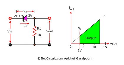
Using a Zener Diode as a Voltage Detector
Another application of a Zener diode is utilizing it as a voltage detector, where its breakdown voltage serves as the minimum threshold, as illustrated in the image below.
When Vin exceeds the Zener diode’s VZ, 3V, a voltage will be produced at the output. Now, the Vin and Vout are directly linked with each other; in other words, Vin and Vout will increase and decrease by the same amount.
As a result, we can easily use a Zener diode’s VZ to detect voltage.
Simple Voltage Level Indicator using Zener Diode
This Simple voltage indicator is another application of a Zener diode. The LED will only light up when the input voltage exceeds the VZ of the Zener diode combined with the voltage of the LED itself.

For example, consider a 3mm red LED that requires about 1.7V and 10mA of current. If we were to use a 3V Zener diode, the LED would light up when the supply voltage exceeds 4.7V (1.7V + 3V).
With this type of circuit, we can use a Zener diode to check or measure voltage and use an LED as an indicator, for instance, in meters or a battery tester.
Side note, if a Zener diode with the exact value is not available, we could also change the resistance of RS using the following formula: RS = (VLED + ZDV) ILED
Automatic Battery Charger Circuit

In this circuit, the Zener diode ZD1 connects between VR1 and SCR2; ZD1 conducts current to SCR2, allowing it to conduct current. With the following important conditions: the current flowing through it must be more than 5mA, and the voltage needs to be higher than VZ1. For example, the voltage across the adjust pin of VR1 and GND is higher than 8V, which is higher than the VZ of ZD1 by about 1.2V. As a result, the voltage flows from ZD1 to G of SCR2, so it conducts current, and LED2 thus lights up.
Read more details about this circuit here: https://www.eleccircuit.com/automatic-battery-charger-circuit/
Anyhow, using a Zener diode as a voltage detector has one glaring downside: its accuracy. It is thus not suitable for applications that may require high precision; in those applications, it is better to use a proper voltage comparator.
Conclusion
This is a summary of the details regarding the Zener diode. Although this component may have been considered ancient by now, it remains useful to this day. In some applications in which we may not want to use complicated components, we could just use this simple Zener diode instead. And importantly, it is easy to use, unsophisticated, and durable.
Maybe in the future, we will bring back the Zener diode to use again, but now integrated within an IC. We hope that this article seems useful to you.
GET UPDATE VIA EMAIL
I always try to make Electronics Learning Easy.

I love electronics. I have been learning about them through creating simple electronic circuits or small projects. And now I am also having my children do the same. Nevertheless, I hope you found the experiences we shared on this site useful and fulfilling.


I am 72 years old but I always like electronics I don’t know that much but I find it interesting.
Regards Roger.
Hi Roger,
Thanks so much for your feedback.
It makes me so happy.
Did you know that You are the same age as my father?
I promise to make electronics easy for you.
I hope my dad likes electronics like you. Because it could help reduce his memory loss. You probably have a good memory, right?
Thanks again.
Apichet
Good to be among professionals
Hi katongo,
Thanks for your feedback.
Can you explain to me why Basic Higher current Zener and transistor regulator if you should not look at resistor R1 but in transistor to give higher current. Somewhere I have read that resistor R1 is essential to give higher current to a circuit.
Hello Tomasz,
It is glad that you are interested in the power supply. I love it. Yes, In the power supply. We use a Zener diode and transistor often.
A resistor affects the current of the load as well. It passes the current to a Zener diode and most current to the load.
Then, we add a transistor. Also, a resistor is a device that passes a bias current for the transistor to operate. The more current flows through the transistor to the load.
In the past, I didn’t really understand how this works. But when trying to build these circuits, and compare them so more understandable
PS. I am not quite sure. I will clearly understand your question. My English is quite poor.
The water tank zener analogy is not really demonstrative of a zener. A better 1st order anology would be a mechanical spiral tension spring with loops at each end. Then with a bolt through it and a nut setting the max elongation of the spring(to mimic Vzener). Then some mechanism to not allow a reverse elongation as the zener will act as a regular diode if reversed.
Hi,
Thank you very much for your advice.
I’m currently studying about Zener diodes.
Your suggestions are very helpful to me.
And I will learn more.But I am a slow learner and not very good at it. 🙂
The water tank analogy as given is incorrect. The pressure (voltage) on the output is effectively zero unless the tap is so wide open that the water backs up in the can.
A can with a wide overflow at the top so that most of the water flows out will give a fixed pressure (voltage) at an outlet at the bottom of the can, but this analogy also fails because there is no excess current outlet in a Zener Diode.