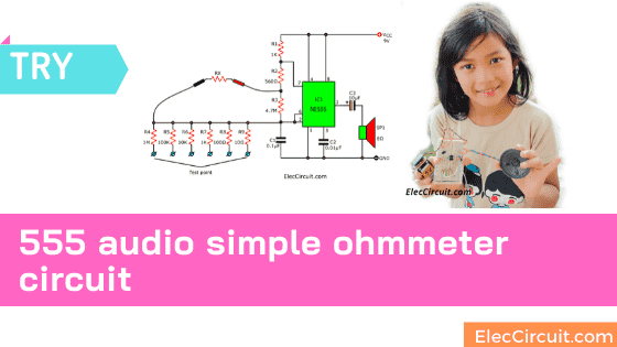
Today I am going to show you, 555 audio simple ohmmeter circuit. Why should you try building it? Besides, it is very easy and still useful. We also learned the principle of 555 timer IC which has many benefits.
What is more? You may have encountered this problem.
You try to imagine There are 2-3 values of resistors in your device tray, (more than 100 pcs) mixed together, such as 100K, 10K, 180 ohms.
Of course, you know that they are all normal. Because it’s just been used. But we will separate it. To store it. For next time easier and worthwhile (Reuse). No need to buy again. How do to do it?
Color code reading May be difficult to distinguish and waste of time. Measuring with a digital multimeter is also a waste of time.
Do you believe it? We are able to distinguish voices better. And, the frequency makes that sound. In normal of oscillator circuit can produce different sounds by changing resistors and capacitors.
This circuit will use the resistors that unknown value to compare with many the reference resistors.
Or Some times, we need to measure roughly the resistances only. In this we can know the resistances by the audio so also fast check.
Recommended: Make Digital ohm meter circuit
How it works
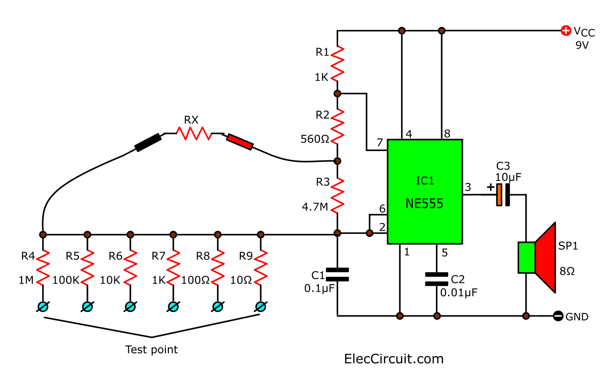
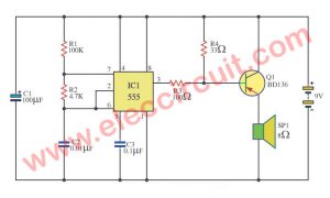
In Figure 1 is the circuit we use IC-555 works as the frequency oscillator circuit. The IC1’s output of IC1 will drive the piezo speaker.
Learn 555 works as an astable multivibrator
The circuit’s frequency will depend on the value of Rx (the unknown resistor) and can be calculated from…
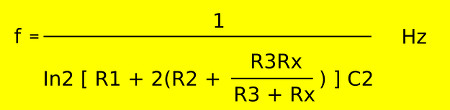
In2 = 0.6931, All resistors have unit in “ohms” and the C2 has unit in “farad”
Then we put the unknown resistor into the RX. The circuit will generate the audio to the buzzer emit by a frequency that we calculate above.
But how to compare various resistors, will easier calculation.
If Rx is zero the output frequency about 4,500 Hz and when Rx is the infinite value, the output frequency will be about 2 Hz.
How to build it
You can build this circuit easily on a breadboard or solderable PC breadboard.
This circuit may help you to have fun. And worth the time Electronic learning.
Parts you will need
- IC1: NE555 timer IC
- C1: 0.01uF 50V Ceramic or mylar
- C2: 0.15uF 50V Ceramic or mylar
0.25W Resistors, tolerance: 5% - R1, R7: 1K
- R2: 560 ohms
- R3: 4.7M
- R4: 1M
- R5: 100K
- R6: 10K
- R8: 100 ohms
- R9: 10 ohms
- SP1: Piezo Speaker
- B1: 9V battery Or 9V power supply circuit
Here are a few related circuits you may want to see:
- Make Police siren circuit using 555 timer, transistors and OP-AMP
- Food & Water Salinity Tester Meter circuit
- Digital temperature meter using LM335 or LM135

I love electronics. I have been learning about them through creating simple electronic circuits or small projects. And now I am also having my children do the same. Nevertheless, I hope you found the experiences we shared on this site useful and fulfilling.