We need to use a 24V power supply circuit for a 30w power amplifier. In the circuit is a fixed DC regulator circuit. Thus, your amplifier has very quality sound more. When the load-use many currents. The output voltage still voltage of 24V, and low ripple. So low noise on the speaker of your amplifier.
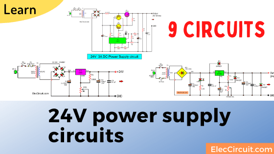
Update: It is better. If we have many ways to do. So let I show you how to choose (or design) the circuit in many cases below!
Of course, These are 230VAC to 24VDC power supply circuit diagrams. We can use these circuits for any jobs and can change voltage output as you need. This circuit has a few parts and is easy to buy in most of the local markets. When we design any circuits. We should use the circuit as a load is required.
Are you a beginner? Learn Basic Electronics
Do not use too over!

It is like riding an elephant to catch a grasshopper. Because it is wasteful and unnecessary.
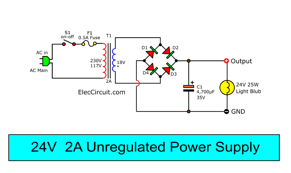
24V 2A unregulated power supply
If your load…
- Use a constant current at all times. For example coils, LEDs, lamps, Resistors, Heating coil, DC motor, etc.
- Has a fixed DC-regulated circuit inside. For example, mini TV, Monitors, and more.
I think an unregulated power supply is enough for your job. It is easy and saves.
Imagine you will try to build small chicken egg pods. You will use a 24V 25W light bulb. Because you have it and direct AC voltage is dangerous for children.

Incandescent bulbs have the advantage. While they light up.
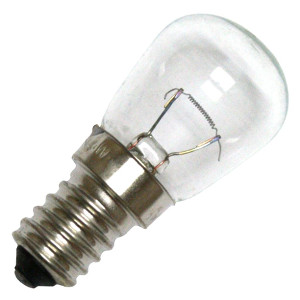
CR: Photo by Norman (affiliated link)
They are also heated. Which is suitable for experimenting with hatching eggs.
How to design circuit
In the circuit, we have to choose 4 components lists.
Read also: Electronic Components list
1. Transformer(T1)—main power.
Look at load: 24V 25W light bulbs. They use current are…
P/V = I
P = 25W ; V = 24V
So, I = 25/24 = 1.04A.
You may use a 1A transformer. But in a long time, it is hot. We should it is at least 1.5 times of load current. Or 1.5A in this case. But we cannot find a 1.5A transformer. So, use of 2A is better. Then, How much voltages of the transformer(ACV)?
As Principle of unregulated power supply DCV is 1.414 times of ACV. When 24V light bulbs. ACV = 24V/1.414 = 16.9V We may use the 18V transformer. If no load the voltage is about 26V.
And In load voltage may be lower 22V. But it can keep light stable. So, we should 18V 2A secondary transformer.
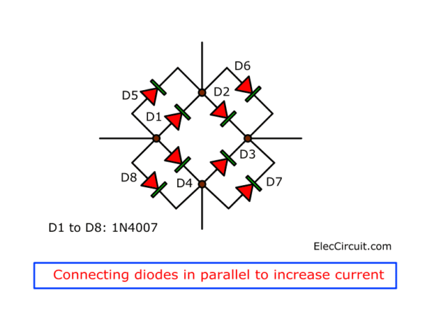
2. Diodes rectifier(D1-D4)—use 2 times of load current. In this I use 1N5402, they can give 3A output. Or you can get 1N4007 in parallel both can get 2A.
3. Capacitor Filter(C1)—It keeps output voltage is stable when using a load. You don’t like to calculate a lot, right? Use 2,000uF per 1A load current right now.
Suppose you use a 1000uF capacitor. The light bulb may be low light. And voltage drops. We need to use more capacitors. You may connect them in parallel to more capacitance. Or the other hand, if you cannot find more capacitors. You may use the voltage of the transformer up is 20V. The voltage is higher. But when no load or low current load. The voltage is 28.28V
More current up
If you want more current up to 5A, 8A, 10A. It looks the same. Such as 5A power supply. You need to use 5A transformer, Diodes rectifier is Bridge 10A 100V. And Capacitor filter is 2,200uF x 5 (in parallel) = 10,000 uF 35V (total).
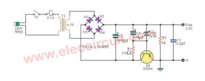
Low current 24V regulated supply
If you have a small load using the current lower of 30mA. You use a Zener diode voltage regulator is enough. Watch in the circuit below.
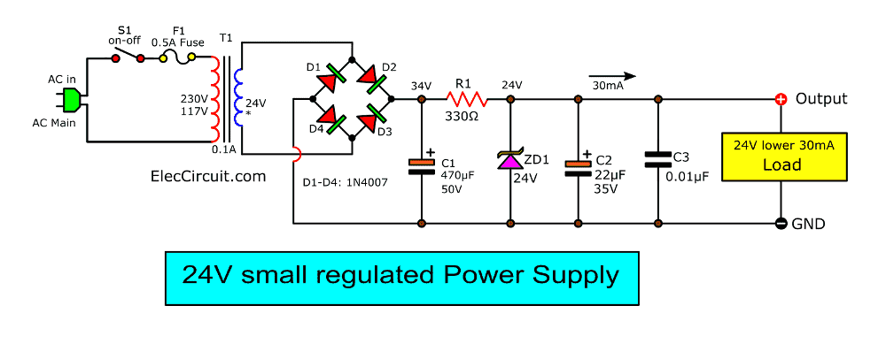
We use 0.1A transformer only, And the power of R1 is interesting. We can find it. With
P = (V x V)/ R
V= 10V, R= 330 ohms.
P = (10×10)/ 330 = 0.303 watts.
If we use 0.25 W, it may be heating up.
You should use 0.5 watts.
C2 capacitor filter is normal to use 0.05 times of C1. C3 capacitor reduces the spike voltage of output.
Here are a few related articles you may want to read:
- How to use Zener Diode, example circuit usage
- Small Zener diode voltage regulator circuit with PCB
- 9V regulated power supply circuit
24V 1A power supply using LM7824
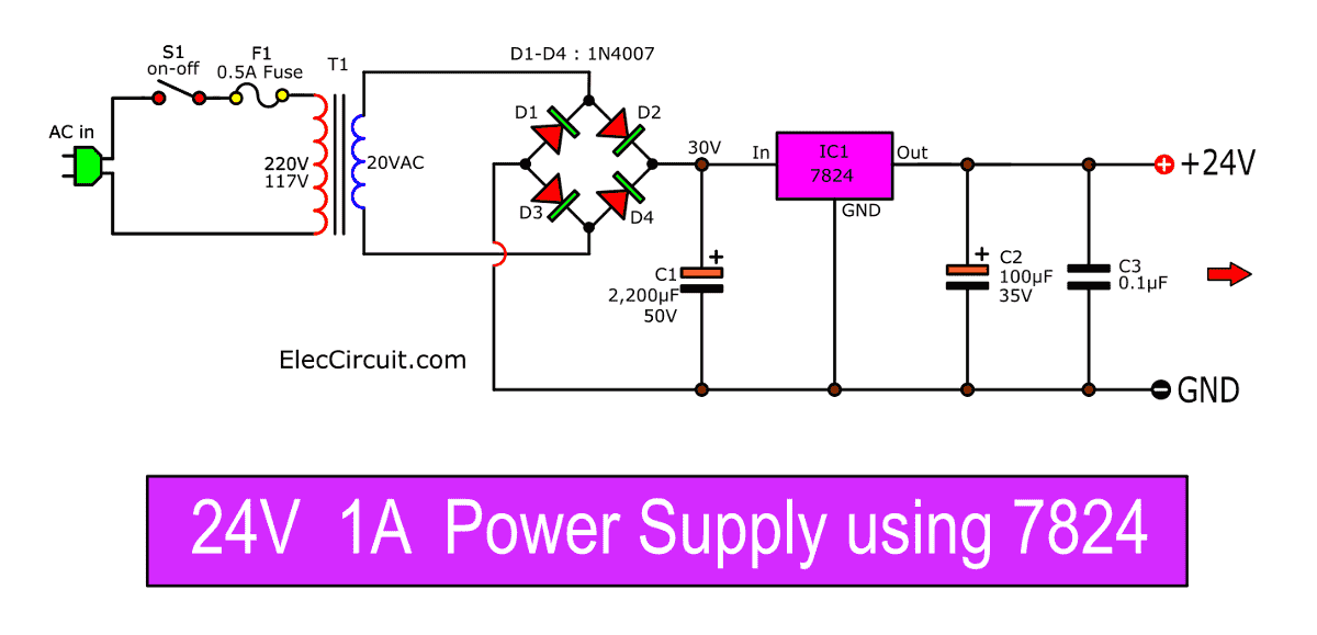
For load use the current lower 1000mA. I think using the LM7824 voltage regulator is best. It is easy and cheaper than a Zener diode and transistor regulator. Look at above 24V 1A power supply circuit diagram.
Others parts in the circuit I use as principle above.
Apply 7805 to 24V power supply
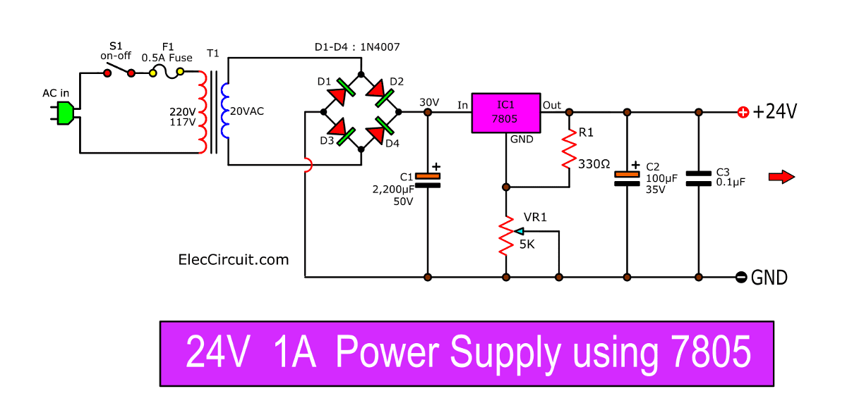
If you have only 7805. But you want to make a 24V 1A regulated power supply. We can do it with potentiometer VR1 and R1-resistors. It is easy but useful. When we adjust VR1 to high or low resistance. The output voltage is 5V. But if we adjust VR1 to low or high resistance close 5K.
Zener-transistor Regulator
24V 2A power supply circuit Diagram
This is a type of series voltage regulator. Some called it Transistor Series Voltage Regulator If you want to learn more…Click
How it works
First of all, we see on the 24 volts regulated power supply circuit diagram. It includes 2 main parts.
1. Unregulated DC power supply.
Here’s the step-by-step process:
- Step-down transformer-T1
- Full-wave rectifier bridge (D1 through D4)
- Filtering capacitor C1.
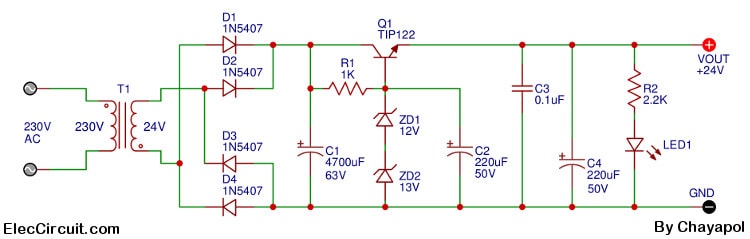
2. The regulated circuit made up of R1, ZD1, ZD2, C2, and Q1.
- Second, we come to see the working of the circuit. When we feed the AC voltage to the power cord, transformer T1 changes 230VAC(PRI) to about 24VAC(Sec).
- Then, the rectifier bridge, D1 through D4, rectifies the AC into pulsating DC.
- Next, A big electrolytic capacitor-C1 filters the pulsating DC to a smooth DC voltage of about 36V. But this is not complete. Because It is not DC regulated voltage of 24V at 2A.
After that, the DC voltage flows through the R1 to Zener Diodes (ZD1, ZD2) to keep the voltage constant at 25V. This voltage across the base of Darlington transistor Q1 to bias it working full current more than of 2A.
The capacitors C2, C3, C4 acts as a storage capacitor to reduce the noise of output. This makes the constant voltage across the output of 24V. The LED1 shows power on of circuit, and the R3 is its current limiting resistor.
Parts you will need
Q1 = TIP122 or simillar, 45V 4A NPN Transistor
D1-D4 = 1N5407, 1000V 3A Rectifier Diodes
ZD1 = 12V 1W, Zener Diodes
ZD2 = 13V 1W, Zener Diodes
0.5W Resistors tolerance: 5%
R1 = 1K
R2 = 2.2K
Electrolytic Capacitors,
C1 = 4700µF 63V
C2 = 220µF 50V
C2,C4 = 220µF 50V
C3 = 0.1µF 50V, Ceramic Capacitors
LED1 = Red LED, 5 mm
T1 = 230V AC primary to 24V,3A secondary transformer, Quantity: 1
24V 3A Power supply circuit diagram
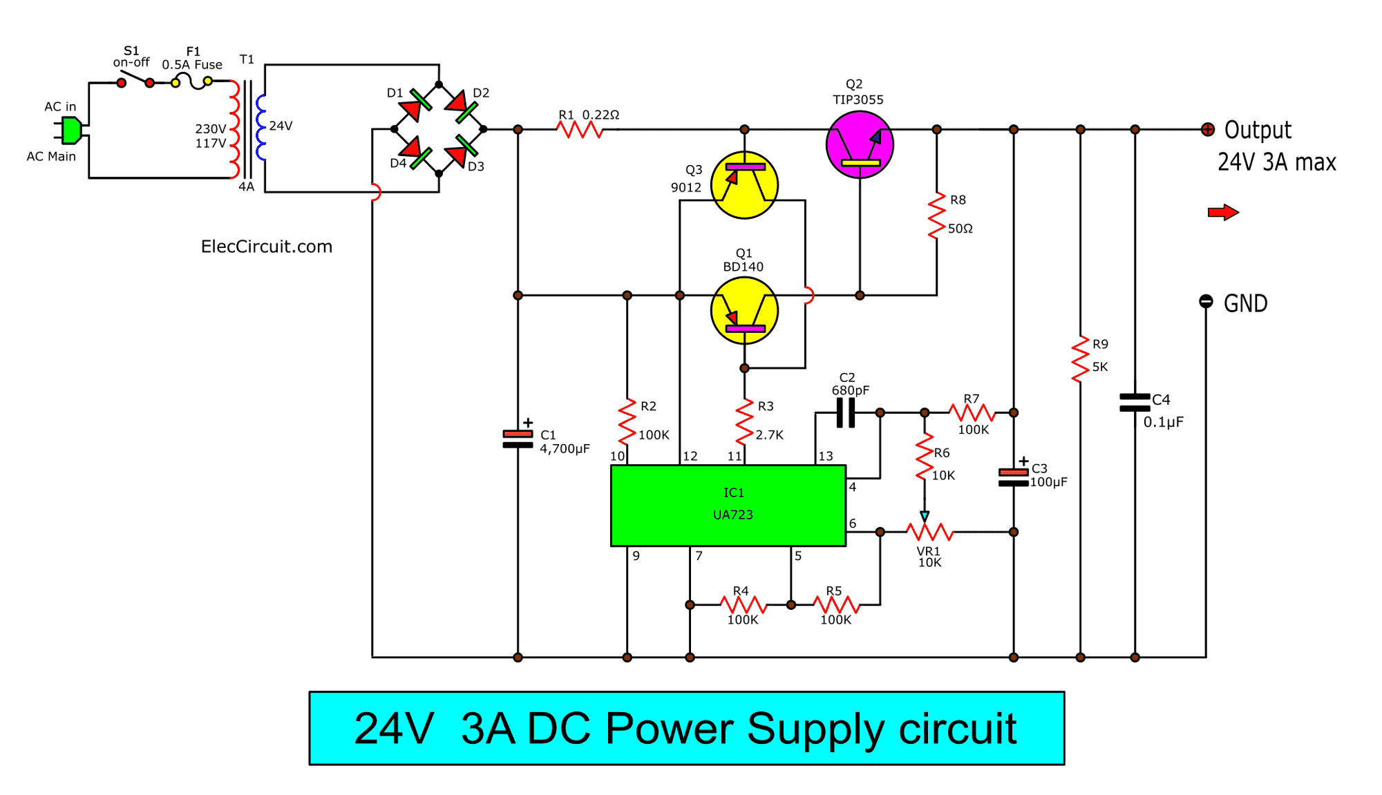
Some have a load circuit that requires a 24V 3A regulator. We have many ways to do it. But this circuit below. You may like it.
We can adjust the output voltage is 24V at 3A current.
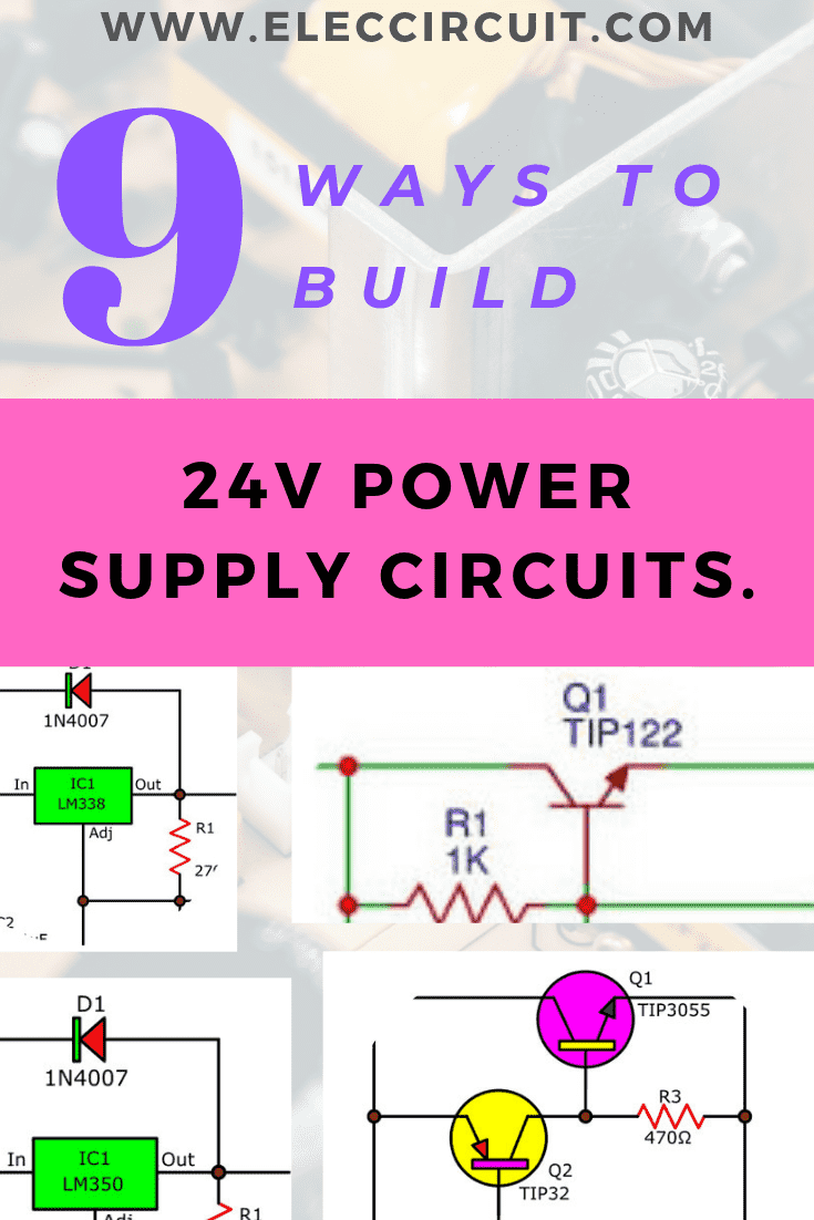
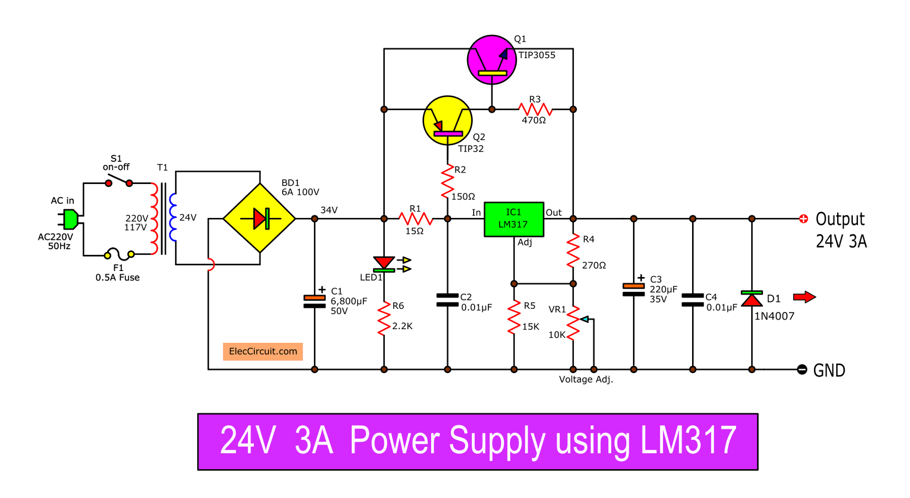
24V 3A Power Supply using LM317
In normal we can use an LM317 voltage regulator to give 24V regulated supply. But it can give on 1.5A max. But if you need 3A. We can apply transistors Q1 and Q2 to increase current to 3A max.
Parts list
5% Resistors, tolerance 5%
R1: 15 ohms 5W
R2: 150Ω
R3: 470Ω
R4: 270Ω
R5: 15K
R6: 2.2K 2W
C1: 6800uF 50V Electrolytic capacitor
C3: 220uF 35V Electrolytic capacitor
C2,C4: 0.01uF 100V Ceramic
BD1: 6A 100V Bridge diode
D1: 1N4007 Diode
LED1: Red LED
Q1: TIP3055, 15A 60V NPN transistor
Q2: TIP32, 4A, 40V PNP transistor
VR1: 10K Pot potentiometer
T1: 230V AC primary to 24V,3A secondary transformer
Note: I apply this circuit from 2N3055-LM317 3A variable power supply
Easy 24V 3A regulator circuit using LM350
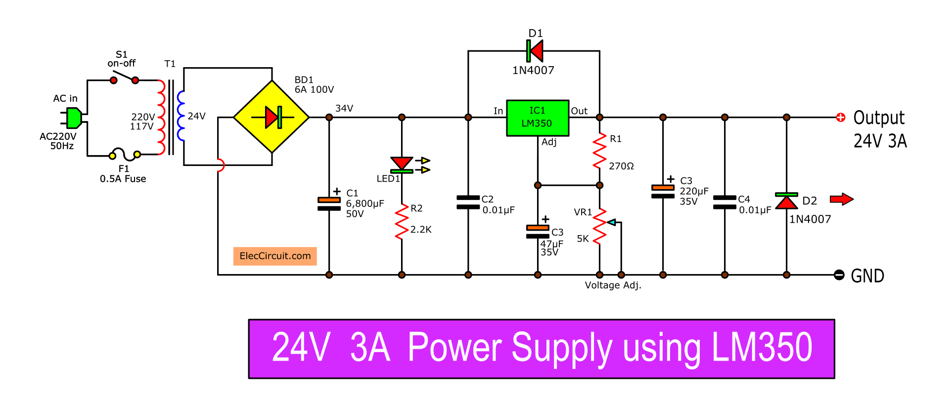
If you want a 24V 3A regulator that easest. Use an LM350 Voltage Regulator IC. Watch circuit above. Adjust VR1 to control the output voltage to 24V 3A.
5A 24V regulated power supply using LM338
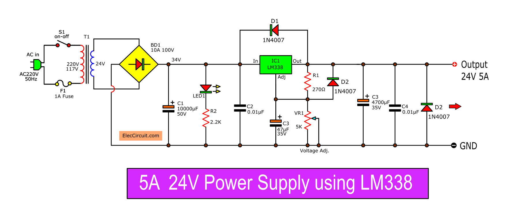
Then if you have a load that uses 5A current, 24V fixed voltage. I recommend this circuit. We use the LM338 voltage regulator. It is easy like LM317 or LM350. But it can give high current up to 5A.
You need to use 5A transformer. Watch the above circuit.
Read more: ‘0-30V 3A Power supply’ »
GET UPDATE VIA EMAIL
I always try to make Electronics Learning Easy.

I love electronics. I have been learning about them through creating simple electronic circuits or small projects. And now I am also having my children do the same. Nevertheless, I hope you found the experiences we shared on this site useful and fulfilling.
Hello sir how much cost
24 volts SMPS 2.5 amp
For ro water purifier required
We currently do not have a 24V 2.5A Switching regulator supply circuit on our site.
But this circuit is quite interesting, maybe in the future, we will make one.
Please stay tuned.
need some help can you email me your email address so that I can send you the data
Hello Sameer Khurana,
Please email me: [email protected]
Thanks
Please give the circuit diagram of the negative output power supply on 24VDC/ 3 Amper current holding capacity. Also, let me know the reverse/ negative IC o/p of LM350 IC.
like