NE5532 Pinout Datasheet Dual low noise op-amp
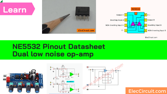
NE5532 is in Hi-Fi audio system a lot. Why? Read this datasheet, Get pinout, spec, how to use. For example preamplifier with tone control. Read more
NE5532 is in Hi-Fi audio system a lot. Why? Read this datasheet, Get pinout, spec, how to use. For example preamplifier with tone control. Read more