Transistor equalizer circuit diagram
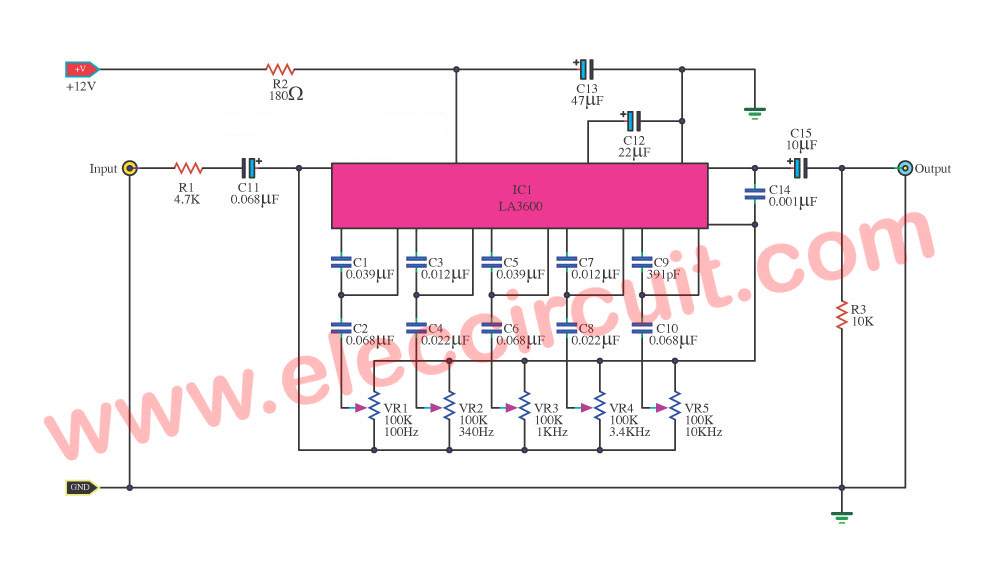
Here is the transistor graphic equalizer circuit. Why should make this circuit? We use it for controlling the audio frequency in some kinds of audio frequency responses that are not flat. Which we cannot use a normal tone control circuit. Because it has a too wide bandwidth. We need to use a good equalizer circuit … Read more