This circuit is a simple mixer circuit. It can mix two signal channels and one channel is output. Using a codec circuit, Convert stereo audio to mono audio time.
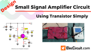
Simple FET Audio Mixer Circuit
In-circuit a FET number 2N3819 is main, it is better than common transistors that a high impedance input and high gain too. so cause low noise.
It can increase the number of channels too, By adding a VR1, R1, and C1 to the amount needed. Then connected to Buffett a new one. Most important it uses very low current with 9-volt batteries immediately.
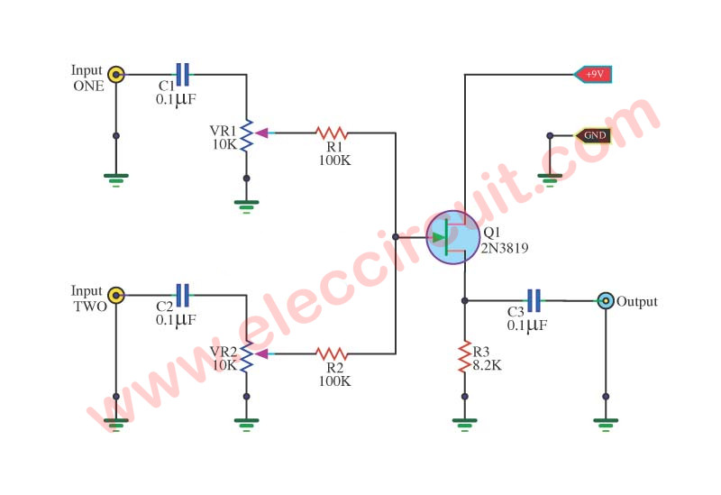
When entering the audio signal, one of input 1 and input 2. Audio is via C1 and C2 of each channel, served coupling signals to VR1 and VR2. To adjust the audio to the Fet Q1.
Which it serves, including audio. Then expand signal the output pin S through C3 For coupling signal again, before leaving to the output.
This is the idea of the simple audio mixer circuit. Perhaps you might need to take advantage of it.
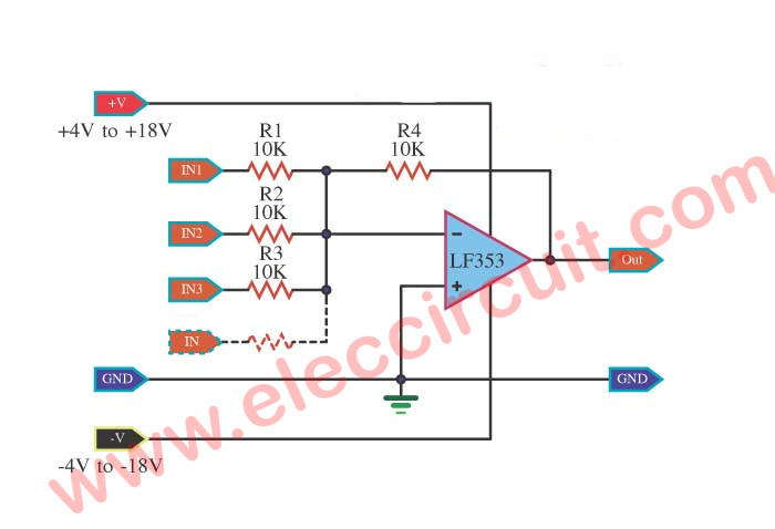
Sometimes you want high gain than FET, I think an OP-AMP IC is a good way for you. The LF353 has JFET within it so very well the same common FET but it has many components inside it, makes high gain, and better than 2N3819 but in normal using we may need it because too cost in some places.
Audio Mixer by IC LF353
This is a very simple 4-channel audio mixer. We used a number IC of LF353 is the main equipment, the function of each channel combined with upper signal level. They is low noise for J-fet op-amp IC (NO. View to LF353)
Audio Mixer by IC LF353
3 CH MIC preamplifier with Mixer using LM348
If you are looking for a mixer with a microphone, and can easily make your own.I highly recommend this circuit.It is a microphone pre-amplifier for 3-channel or 3-channel mixer itself. When looking at the circuit, we have featured the use of a single integrated circuit LM348. The internal structure of the four IC-741 ICs. When It costs was similar, thus allowing us to save all of IC-741 and convenient to use than one x 4pcs.
-This is the Universal mono preamplifier using ic LM741
And we can adjust the volume, each microphone freely by VR1, VR2, VR3. But this circuit used to the dual power supply +12V -12V and GND that should be dc voltage regulator with IC-7812,7912 or transistor follows you want.
–Power Regulator +12V_-12V by 7812 , 7912
You should preamplifier before enter single to power amplifier because the out of this circuit is low power.

Circuit of Mixer Pre MIC (microphone preamplifier) 3 Channel by LM348

PCB of Mixer Pre MIC (microphone preamplifier) 3 Channel by LM348
Micro mixer circuit using TA7137
If you are looking for a micromixer circuit that create a simple, affordable, small and compact, and be usable versatile, must be this circuit. We can use to mix up to four input channels such as the microphone signal, FM Tuner, AUX and Other signals, As the circuit shown in Figure 1.
How it works
The input signal Input signal in each channel is entered through R1, R4, R6, R8, respectively, to potentiometer VR1-VR4. which is Adjustment value of Signal in each channel is the right size. Then is entered through a R2, R3, R5, R7 in together, and then pass through C1, R9 to input of IC1.
– The IC1(TA7137) is an amplifier signal that was introduced all together, Until the output signal at pin 8 through C7.
– The R14 and VR5 It is the adjusted strength of the total output signal.
– The C3, C2, D1, D2 are feedback circuits for control gain of circuit to has level constant output signal.
– The LED L1 is a signal meter display that it flashes by the signal strength of the input voltage applied to the circuit.


– We chose pack 9 volt battery as the power source of circuit so convenient to use.
Figure 2 PCB layout and positioning equipment.
The detail parts
IC1: TA7137 PRE-AMPLIFIER(RECORDING OR PLAYING-BACK WITH ALC TRANSISTOR FOR TAPE RECORDER)
D1, D2: 1N4148, 75V 150mA Diodes
L1: LED 2×5 mm
0.25W Resistors, tolerance: 5%
R1, R4, R6, R8, R12: 10K
R2, R3, R5, R7, R9, R14: 1K
R10: 18K
R11: 1K
VR1, VR2, VR3, VR4: 5K-10K, Potentiometer
VR5: 10K SW.
Capacitors
C1, C8: 4.7uF 16V Electrolytic
C2, C3: 0.0033uF 50V Polyester
C4: 30pF 63V Polyester
C5: 47uF 16V Electrolytic
C6: 100uF 16V Electrolytic
C7: 3.3uF 16V Electrolytic
How to build
We install all the components on the PCB correctly completed. According to the circuit in Figure 2. When finished we can install it in a box ready, for ease of use.
In installed in the box, should be unloaded VR5 from PCB to hold separate. We can hold PCB to the box, withholding the potentiometer VR1-VR4 to box there.
Then we remove the LED L1 out a way, to hold at the box. And then we wiring to the equipment Jack and the PCB orderly.
Related Posts


I love electronics. I have been learning about them through creating simple electronic circuits or small projects. And now I am also having my children do the same. Nevertheless, I hope you found the experiences we shared on this site useful and fulfilling.
I am trying to make the Simple audio mixer circuit with fet 2N3819 but don´t work. I had make a PCB for this project. Someone has done the project??