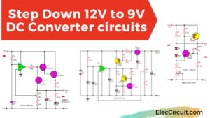
This boost converter circuit can convert a 12V 10A input into a maximum 24V 5A output. The output voltage can conveniently be selected from many ranges: 18V, 20V, 22V, and 24V. The circuit is also relatively easy to make and assemble. The full specification is listed below.
Feature of This Circuit
- Input Voltage : 12V 10A
- Minimum Output Voltage : 13.6V
- Maximum Output Voltage : 26.3V
- Selector Voltage : 18V, 20V, 22V, 24V
- Maximum Output Current : 4A-5A
When using a laptop in an area without electricity, we would normally have to rely on the integrated battery, which at best would last a couple of hours. So, if we want to use it for an extended period of time, we will need to connect it to a power source.
In this case, we would use a solar cell and battery system. However, that system alone can only supply a voltage of 12V, and according to the laptop’s charger, it requires a voltage of 19V 3.8A to charge. Therefore, we need to find a way to increase the battery voltage.
The best way to increase battery voltage is to use a boost converter, which we would often choose the MC34063 because it is easy-to-use and inexpensive. However, the MC34063 by itself can only supply a maximum current of 0.5A.
Thus, to amplify the current, normally we would use a power transistor, but this time we will use the MOSFET instead, because it works well with high frequency, can drive high current, and is relatively easy to use.
The Circuit Structure
I got this boost converter circuit from a local electronic store. It can convert a 12V input to 18V, 20V, 22V, or 24V outputs, which is in line with the initial requirements we set earlier.
But I still think it would be interesting to learn how the circuit works, so let’s start with the block diagram.
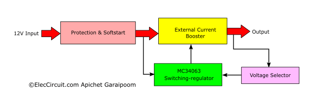
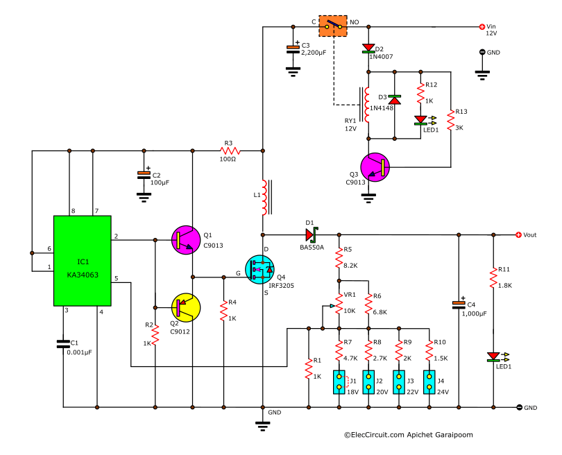
The Protection & Softstart
A circuit that has high current should also have an adequate level of protection, especially against shortcircuits, which can cause significant damage to the IC and other semiconductors.
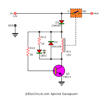
(1) When supplied with the correct polarity of current, the positive current enters the circuit through the D2 as a base bias current for the Q3, causing the Q3 to turn on and function similarly to a closed switch. (2) As a result, current flows through the relay’s coil, causing contacts C and NO to close. (3) Allowing the remainder of the current to flow to the boost coverter circuit. Meanwhile, the LED1 lit up, indicating that the circuit was working.
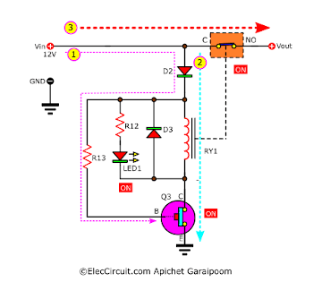
The circuit would not let current through if the following conditions were met:
- Vin is less than 9V; the voltage is too low, causing the relay coil to not be able to pull in the contacts.
- Vin is reversed polarity; the negative voltage cannot pass through D2 or it received reverse bias.
Basic MC34063 Switching Regulator
Now we moved on to the basic MC34063 switching regulator part. It consists of a few important components, such as C1, C4, D1, L1, and the MC34063 itself.
C3 helps keep the current smooth during a spike in load current; without it, the load might get damaged. C2 and R3 filter the current for the IC1, thus improving the overall efficiency of the circuit.
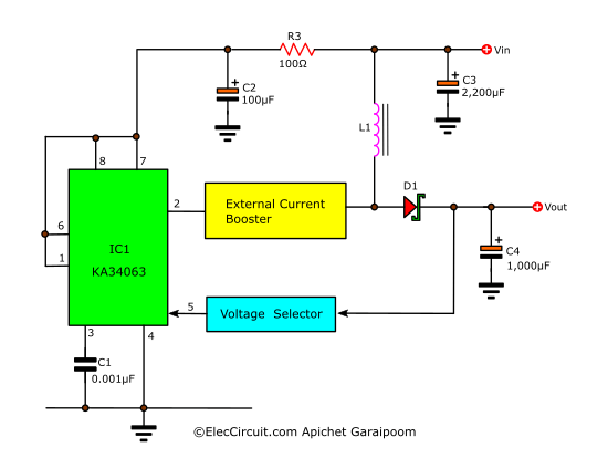
The External Current Booster
Currently, the circuit can only supply a maximum current of 500mA. So, we will have to use an external current booster; it will amplify the current to around 4A, which is what we need.
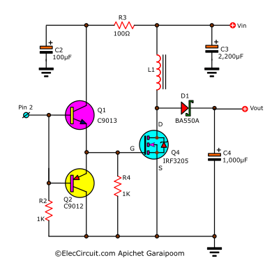
In the above circuit, Q1 and Q2 work together as a push-pull preamplifier, which increases the effciency of amplifying the AC signal. The preamplifier is then connected directly to G of the MOSFET, thus allowing better amplifaction of high-frequency signals. Also, the MOSFET biases with voltage, meaning that it can drive current through L1 and D1 at its maximum potential.
The L1 is 0.03mH or 30uH, capable of withstanding a current of 5A. The D1 is BA550A, which can withstand 5A current and 150V.
While the Q4 is IRF3205, it has the highest drain-source (VDS) of 55V and continuous drain current of 110A. This MOSFET is often found in an inverter, and it is also inexpensive. Lastly, R2 and R4 are there to increase the stability of the circuit.
Voltage Selector
Next is the resistor voltage selector circuit; it is used to set the output voltage of the circuit. It can select between 18V, 20V, 22V, and 24V by using J1 through J4. You can also use the VR1 to fine-tune it further.
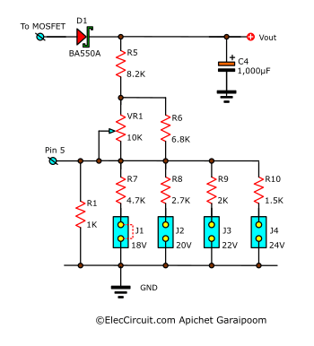
For instance, if we jump the J1, the output voltage will be about 18V, and we can use the VR1 to adjust it to any voltage within the 18V range. The lowest output voltage is 13.8V, while the highest is 26V, which means that we can set it to match the laptop power supply of 19V.
Complete Circuit
Now we combine every part together into a complete High Current 12V to 15V-24V Boost Converter Circuit.
Testing the Circuit
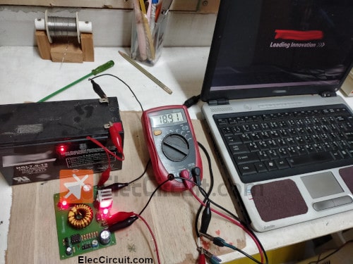
We test this circuit by using it to power an old laptop with a 12V/7A battery as a power source. We selected the J1 (18V) jumper and adjusted the VR1 until getting the 19V that the laptop needs. Then plug it in to the laptop; it works quite well, though the output voltage did decrease by a little bit to 18.91V.
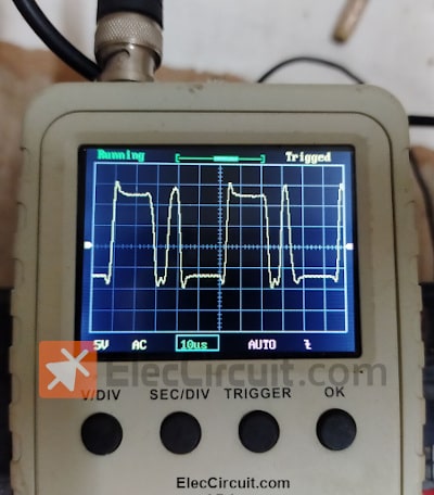
We want to know the signal wave between the D and S of the MOSFET, as it can indicate if the switching circuit is working correctly. When the load requires a lot of current, the frequency will increase as well as the signal level (Vp-p); the result we got is a frequency of 30kHz to 100kHz, as shown below.
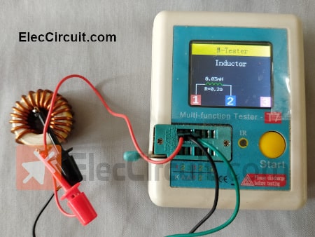
When the circuit is operational, there are two notable heat-generating components, which are Q4 and L1. In addition, measuring the L1 inductor yields a value of 33uH and a resistance of 0.2ohm.
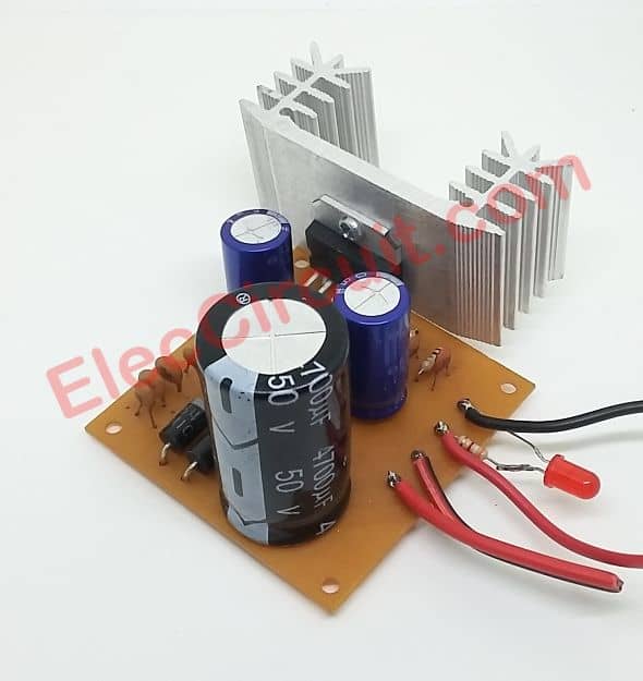
Also, if you have a TDA2004 and want to try the circuit below, it is interesting, but the efficiency is lower than using a Switching mode regulator circuit because it operates at a lower frequency.
Buy a 12V to 24V step-up converter at Amazon HERE
Simple 12V to 24V Double Voltage Converter Circuit
Do not be surprised. If see TDA2004 is in the circuit. Even it is good at the mini amplifier.
It is really, really. We are building a type of switching regulator with it.
We use it to produce the high current pulse to the simple double voltage circuit. Which they work with the capacitors and diodes.
This does not need to use any coil. So, easy and cheap. And, Imagine when you finish this DC converter job. You are bored. You can rebuild it into a nice amplifier.
This project can increase the DC voltage from 6V to 12V, or from 12V to 24V. It is a simple DC to DC step-up converter circuit.
The working principle
First of all, the voltage comes to the circuit. Then, this voltage will charge to C5 through D1. At the pin 10(output) of IC1/1 has the voltage rises up. Until almost equal to the voltage of the power supply.
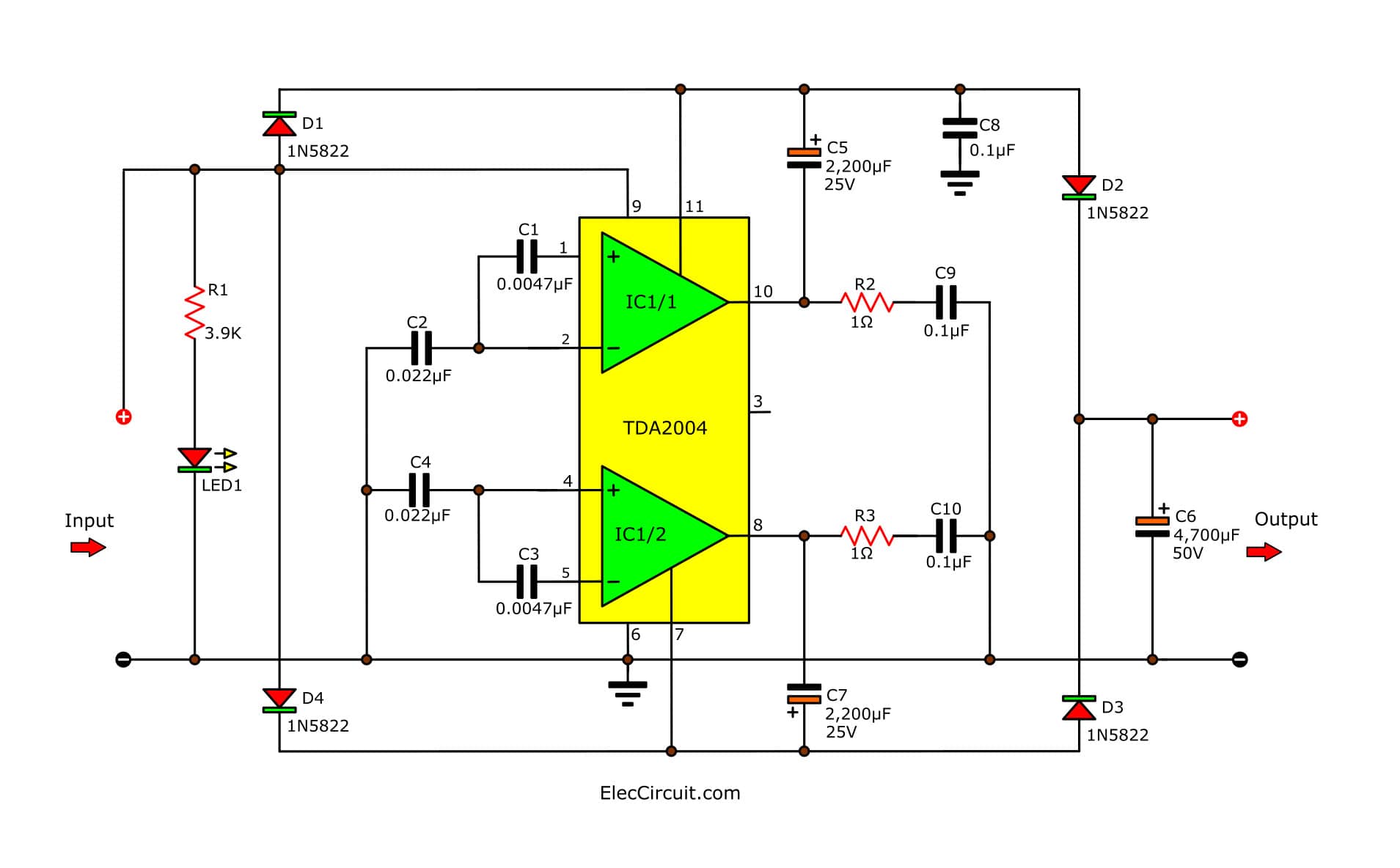
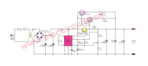
Circuit diagram of step-up DC converter using TDA2004
Next, D2 passes the current to charge into C6. It makes the voltage at pin 10 of IC1/1 about 0V. However, the voltage across C6 or the output is equal to the power supply.
After that, the output(pin 8) of IC1/2 starts to have the voltage rise instead. Because C5 stops charging, so, C7 is charged instead, through the power supply.
Thus, there is the current pass D3 to charge into C6. And, pin 8 has a voltage of about 0V.
Then, the operating of the circuit will restart same the first again.
And, both current get out of pin 8 and pin 10 will be combined at C6.
This makes the output voltage to rise up to 2 times of input. Because the voltage of pin 8 and pin 10 are the input mixes together.
The capacitors C1 through C4 act as a square wave generator about 5 kHz. To determine the working of IC1.
Building, Testing, and Application
When we get fully equipped, and build PCB as Figure below. And then, soldering equipment as Figure.
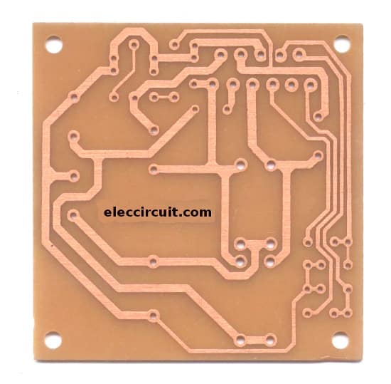
PCB of 12V to 24V step up converter circuit using TDA2004
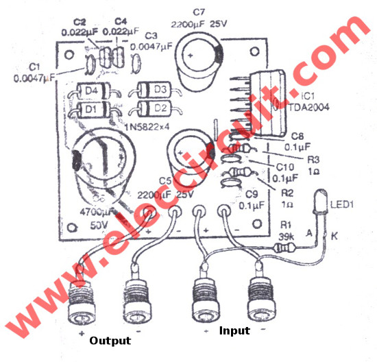
component-layout of the 12V to 24V step up converter circuit using TDA2004
After examining the faulty circuit. Then test them with 12V battery at the input and measure voltage output will have about 22V. Please watch a video below.
If you have a 6V input. It can increase the output voltage is 12V. Or, enter the input is 12V, the output is about 24V.
Conclusion
In conclusion, this above circuit works quite well; it is suitable for increasing a voltage of around 11-13V to 24V, or at not more than 26V, while powering a load of less than 5A. It is also a great example of an easy MOSFET circuit that can handle a high-frequency signal. In the future, we may be able to, for example, further increase the voltage by utilizing multiple MOSFETs connected together in parallel. We hope that this circuit will be of use to you. Thank you for reading.

I love electronics. I have been learning about them through creating simple electronic circuits or small projects. And now I am also having my children do the same. Nevertheless, I hope you found the experiences we shared on this site useful and fulfilling.
I want buy DC to DC convrter.
Best Regards
Hi, Mr.Thamer.
You welcome.
I am glad to it was helpful for you.
I think the parts on this circuit can buy easliy at a common electronic shop.
But this circuit as idea from the old book.
Which may be have error I must sorry.
If you want definite project may buy at amazon.
Best Regards
momename
dear sir
I want to purchase dc 12v to 24v 6A step up convertor and dc 12v to malty dc volt lake 5v,12v,+-,and 48v+-,1A step up convertor if have PLZ send mail this email id thank.
interesting circuit..!
I’m looking for a DC to DC 12 to 24 volt 720 watt power converter if you have or know someone that does please let me know you can contact me at 312-953-0360 Thank You
i will try this today..
i made this circuit its work great no problem i like this circuit very much thanks to http://www.eleccircuit.com
Hi, Sk sahabaj.
Thanks for your feedback.
I am happy that hear you say.
I will keep to showing really test more projects.
can you please post the pcb layout
Hi,nyabraham
No, You cannot. I am sorry ,do not have it now.
Whats the max o/p current
I like really what you do,
because it is clear and useful, for everybody.
Thank you very, very, much
Hi,Prits.
Thanks for your feedback.
I am not sure how many a output current.
But it would not exceed 1A.
Hi, Paul Baround
You’re welcome. I am happy for you.
how many watts in this circuit ??
thank you
Hi,
what is the diode D2 and D3? I do not know where buy it. In the store do not have it.
I can put there some other diode?
My email: [email protected]
Thanks for answer 😉
Nice web
Hi Kamel,
Thanks for your feedback, about within 5W
Useful and good info.
Dear Momename,
Good site of yours.
If possible, can you also post a reliable circuit diagram for a DC to DC converter with input of 12 volts, output of 0.700 A or 1 ampere, this will serve me as driver of 30 Volts, 30 watts LED. Or do you have any alternative simple circuit to post?
Thanks .
U guys should try this curcuit…it able to supply 19.75-21.35vdc full load (2.2A-3A +/-) from 12v psu rail as the input supply(Main supply).I have try on tda2004 and tda2005…My choice is TDA2005.More stable,low heat for powerup my PArig.Nice for power up tda2030 curcuit…
-I have make this curcuit and power up tda2030 x 3 // 1-right //1-left// 1-subwoofer*L/R* //. no problem to power up speaker from altec lansing vs 4621..(this prototype also use 3 x UTC2030 as the amp..)
sorry for my english coz it terrible 😛
On my dc -dc converter using tda2005 i change the D1- D4 (IN5822 or IN5402) coz it bit expensive on my country then hard to find…to solve this problem i use 16pcs IN4007 :(…. for D1 i place IN4007 x 4 on parallel. So on with D2,D3 and D4..for the 4700Mf cap i use 2200mf x2 + 1000Mf x1..(5400mf)//50V..
On load 19v – 21v (2-3amp +/-)…from 12vdc psu for input supply at 11.9-12.8v…My curcuit connected with my computer on same PSU 550W :(….almost 1 year no problem until now..*sharing the PSU :D*
Next i will test/try build 40V – 46VDC using TDA2005 and TDA2009 with same compenent..TDA2009 can handle max voltage 28v/.I guess when combined tda2005(12v to 22v) and tda2009 (22v to 44v +/-) 2-3Amp.. CPU*PSU (12vDC) —-> TDA2005 (22vDC) —> TDA2009 (40vDC – 46vDC)
12VDC// MAIN ————-> 1st_Stage BOOST —-> 2nd-Stage BOOST// 40VDC > +/-
TDA2009A at 24vdc input —> boost to –> 47v – 48vDC output..
Pin 7 and pin 11 (N.C) so no bootstrap, but still working same TDA2004 schematic on dc to dc..I try push on max 28VDC input –> boost to –>56vDC output but it burnout after 4minutes..with big heatsink…….So my recomanded max input voltage dont push it more then 25Vdc..It stable on this input with nice 2A -2.5A..:P
any one help in to convert 12v dc to 36v dc ?
i need circuit diagram
I WANT ONE 12 VOLT TO 24 VOLT WITH 150 WATT CIRCUIT
HOPING FOR YOUR QUICK RESPONCE.
THANKING YOU
Use 2 cheap PSU.12V+12 connect on series.U got extra benifits with this…OC/OV/UC/SC protection with superb current… above 150 Watts
Good Luck…..
hi,
ı must to make a project which is DC to DC boost converter 12V to 24V and 1A. Unfortunatelly ı don’t know what ı need to make project. firstly if you help me for that ı will be so grateful.
thanks…
Use electronic diagram above.DC to DC stepup TDA2004.For the 4 diodes use IN4007 x 4 pcs.This diode deliver 1A.So i guess u should get 24V 1A with the curcuit from pc psu 12V rail or use transformer that suitable for the input for u project.
If you want more AMPS i guess you can add 1 power transistor TIP3055 and power resistorfor support TDA2004 to increase the current(AMPS).For that you need to tweak TDA2004 DC to DC stepup curcuit a little bit. 😀
It is good idea. Thanks a lot.
Pls make suggestion:
We have 4 standard alternators. standard car type, we need an output to drive our 20 Kw motor. We also have 4 x 100amp/hr batteries.
Now 12 v motors appear not to good, better to use 48 v or maybe 72 v.
How do we this to work and what would it cost.
Regards Harry
MEG-Tech
I want to devlop 12 v to 48 v boost converter so can you give me circuit diagram
Hello sir thank you for the circuit…. But can I change (D1-D4___1N5822/1N5404) with 1N4007
I am using this circuit, but the output is out 5-6 volts, what is wrong?
I use this circuit, but the results came out 5-6 volts, what’s wrong?
Thanks