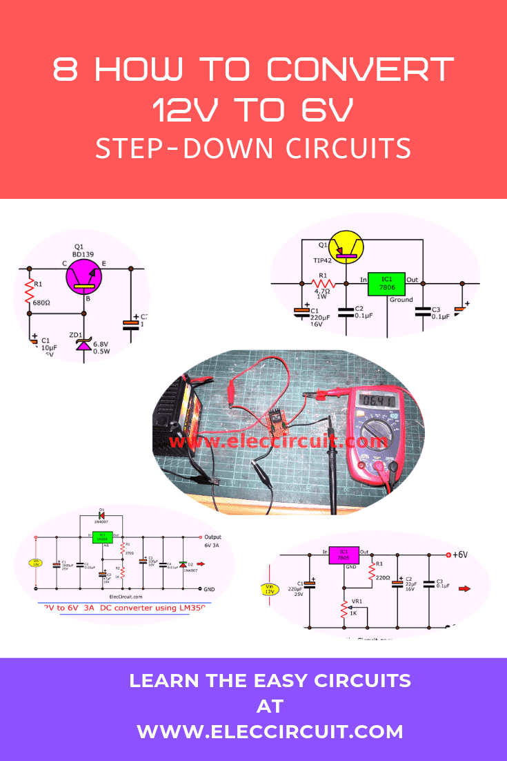
Connecting a 6V load to a 12V power supply will cause that load to run very hot. This article will show you 8 ways to make a 12V to 6V converter circuit that will help you avoid this problem.
I try to show you many ways to do it. You can choose the best for you. For example, you have these parts, or it is easy, or cheap. You can build them as you need.
Limiting current resistor
If your load only requires a constant current, for instance, an LED, light bulb, relay coil, etc., then you could use a current-limiting resistor connected in series with the load.
It is the simplest and easiest way to convert a higher voltage to a lower one, although there are downsides to doing it this way, which we will discuss later.
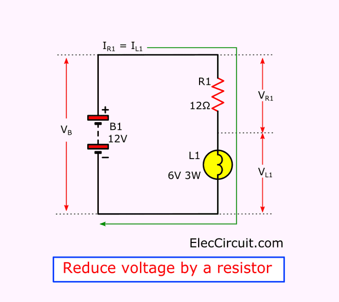
For now, suppose that we have a 6V 3W light bulb connecting to a 12V battery. Let’s find the resistance of our current-limiting resistor.
Finding the Resistance
First, find the current of the light bulbs or R1:
I = P ÷ V
P = 3W , V = 6V
So, IR1 = 3W ÷ 6V = 0.5A
Then, find the voltage across R1 (VR1):
VR1 = VB – VL
Where VB = 12V, VL = 6V.
So VR1 = 12V – 6V = 6V.
Using Ohm’s law:
R1 = VR1 ÷ IR1
Which means R1 = 6V ÷ 0.5A = 12 ohms.
Next, we need to find the power of the resistor:
PR1 = VR1 × IR1 = 6 × 0.5 = 3W
Therefore, our current limiting resistor is 12Ω 3W.
We see that using a load with a high current requires a resistor with a higher wattage, which means that the resistor gets larger and also hotter.
Furthermore, we also use a resistor to reduce the voltage when using a 6V relay as well.
Downsides of a Current Limiting Resistor
If the load pulls current unevenly, even if that current is very low, we should not be powering that load with a current-limiting resistor. For example, using the resistor with a portable FM radio that may only use 6V 0.1A on average.
But when we turn up the volume, it will pull more current, and the voltage will drop to about 5V, whereas when we turn down the volume, it will pull less current, and the voltage may increase to 8V.
This voltage variable may cause the audio to become unstable. Therefore, we should find other ways to power it.
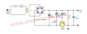
Zener Diode and Transistor Voltage Regulator
I often use this Zener diode and transistor voltage regulator because it is inexpensive and easy to put together. This circuit, in particular, outputs a stable 6.2V at 200mA.
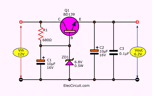
How it Works
First, the 12V input voltage flows through R1 and ZD1. The ZD1 gives this circuit a reference voltage of 6.8V. Then, the Q1 increases the current to the output. The actual output voltage is 6.2V because there is some voltage drop across B-E of Q1.
The BD139 NPN transistor, as used in the circuit above, can only drive a current of 0.5A. However, you could replace it with a TIP41 or 2N3055 transistor for 1A or 2A output current, respectively.
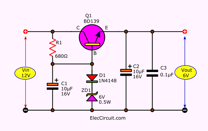
If you need an output voltage to be exactly 6V, you would need to use a 6.6V Zener diode. But, since no 6.6V Zener diode is being built—only the 6V, 6.2V, and 6.8V are available—you would need to add a regular diode in series, as shown in the circuit above.
Fixed voltage regulator working principle
Working principle of unregulated power supply in simple ways
Quick Learn Basic Electronic Components
DC Boost Converter circuit 3-5V to 12V-13.8V
Current limiting resistor for LED and load
12V to 6V Step-down Circuit using IC 7806
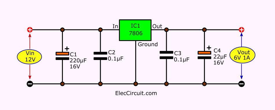
For a proper step-down converter circuit, we would use the 78xx series DC voltage regulator ICs. In this case, it would be the 7806, since it provides exactly 6V output from a 12V input.
This 12V to 6V step-down circuit has a maximum output current of 1A.
12V to 6V Converter Circuit using 7805 and Diodes
However, if the 7806 is unavailable, we could also substitute it with the much more popular 7805 that outputs 5V instead. The 7805 is often used in a digital circuit that requires a 5V input.
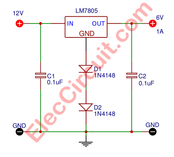
Modifying the 7805 to output 6V is relatively easy; just add 1N4148 diodes between the common pin of the IC and the ground. Each diode will add an additional 0.7V to the output.
In the circuit above, we add in total of two diodes, which results in an output voltage of 6.4V (1.4V + 5V = 6.4V). This circuit is especially convenient if you have the 7805 and a couple of diodes lying around. Additionally, both capacitors are there to absorb the noise and smooth the signal.
Testing the Circuit
Since this circuit only uses a few components, we built it on a perforated board or universal PCB, as shown below. After measuring the output, we see that it is approximately equal to the voltage across both diodes (0.7V + 0.7V) plus the IC output voltage (5V). In the picture below, the digital multimeter reads 6.4V.
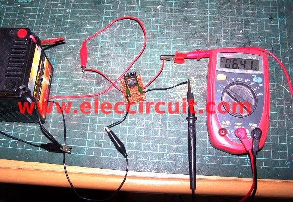
The maximum output current of the IC1 is about 1A, and we should use an appropriate heatsink size for the current being pulled. Also, we could increase the output voltage further to 8V by adding two more diodes.
If the circuit does not work, check if the IC1 is wired correctly. Or in the case that the output voltage is not 6.4V, check if the voltage between the common pin of IC1 and the ground—across the diodes—is 1.4V or not.
Variable Step-down Circuit using IC 7805 and Potentiometer
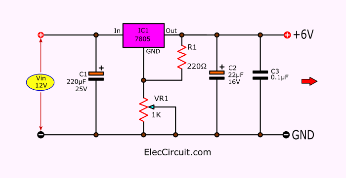
Another way to get a precise and constant 6V output voltage is to add a potentiometer to fine-tune the output voltage to the exact value. In this circuit, we can adjust VR1 to get the output voltage within the range of 5V to 12V.
Buy voltage regulator ICs at Amazon.com here (affiliated link)
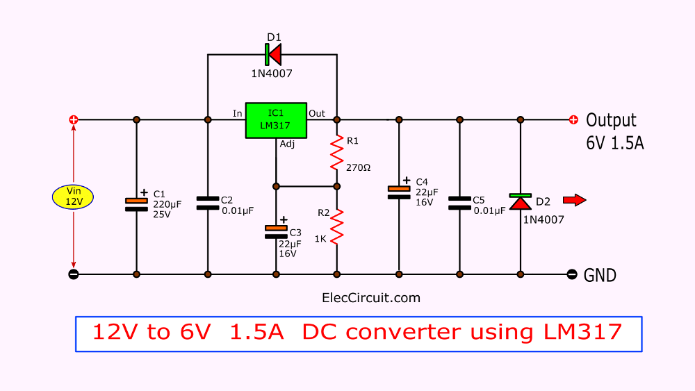
12V to 6V Converter Circuit using LM317
If you want an output current of 1.3A, then you would have to go with the LM317 instead of the 7806. The LM317 can deliver up to 1.5A on its own.
Also, USB 5V to 1.5V Step Down Converter Circuit
12V to 6V 3A DC Converter Circuit using LM350
In the case of 2A to 3A load. We have many ways to do. But first, if you want to build easily. LM350 is best. It is similar LM317 but more current up to 3A max. Look at the circuit below.
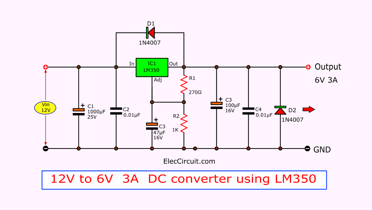
How to Find R2
It would be easier if R2 is a potentiometer, but here are the way to find its exact resistance anyway. We will using the Vout formular for this IC.
Vout = 1.25 x {1+(R2/R1)}
Where Vout = 6V, R1 = 270 ohms.
Substitute those two values in,
6 = 1.25[ 1+ (R2/270)]
6/1.25 = 1 + (R2/270)
4.8 – 1 = R2/270
R2 = 3.8 x 270 = 1026 ohms
Therefore, the resistance of R2 we are going to use is 1K.
Read more: LM350 adjustable voltage regulator
You may also like these:
12V to 6V 2-5A Converter Using Transistor and IC 7806
In case that you do not have the LM350, you could also build a 12V to 6V converter circuit that can output a current of 2A or more using the 7806 and TIP42 or similar transistors.
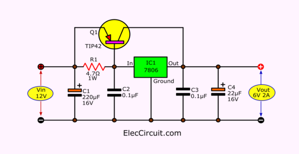
In the circuit above, we used the TIP42, which gives us an output current of 2A. However, you could replace it with TIP2955 or MJ2955 to get up to 3A or 5A of output current, respectively.
Other 12V to 6V Converter Circuits
Here are other voltage regulator circuits that can output 6V.
Conclusion
There are many ways to convert 12V to 6V, each with different current sizes and stability. Nevertheless, we need to choose based on the requirements of our load and the components we would need to build it. Doing that means that we get a suitable converter circuit for our load.
GET UPDATE VIA EMAIL
I always try to make Electronics Learning Easy.

I love electronics. I have been learning about them through creating simple electronic circuits or small projects. And now I am also having my children do the same. Nevertheless, I hope you found the experiences we shared on this site useful and fulfilling.
Hello
I tried this circuit for powering my led emergency light which runs on 6v. As i only have 12v batteryy. At first it worked for 5 minutes then transistor got very hot, i attached a big heatsink with 7805. After few minutes it just turns off. I tried testing voltages using MM. When my led is off it shows voltage of 7.5v(I connected 4 diode), but then as i turns on my lamp, voltage drops to 1.2v? What do u think might have happened?
Hi, Clarkdale44
Thanks for interesting question.
Please Read in text.
I need help! I want to take a 400-500watt computer PSU, use the 12v wire rated at 12-14 amps(there are 2 wires that are powered this way) and reduce it to between 6.8-8.4 volts with a max peak amperage draw of 20 amps. Please help, I found something from the golf cart work that can do this but I’d like to know how to do this so I can make it myself. Email me anytime day or night as this is a pivotal part of my prototype project
i like it
Another Great Project,,,I Love It!!!!!
greet for LM350 it work WITH PLASTIC NOT METALIC ONE
Hello IBRAHIM LAMOOD,
Thanks for your feedback. Yes, LM350T is a great DC regulator IC.
https://www.eleccircuit.com/the-step-down-12-volts-to-6-volts-dc-converter/#6V_DC_converter_circuit_at_3A_using_LM350
It would be nice if someone who wrote English a bit better would edit this. I thank the author, but your grammar is very difficult to follow. I appreciate the attempt!
Hello Scott P,
First, thank you so much. You are very kind for telling me.
I am practicing English regularly. It is difficult and so great for me.
Now I am starting with reading English books for kids. I’m not sure, Is it the right way?
Many people say to keep short sentences. And use simple vocabulary. So grammar will be good, is it true?
If you are free. Please recommend me. How to improve my English in simple ways.
Thanks again.
Apichet
Apichet and Scott,
Maybe it would be nice if someone from America knew enough about electronics to explain it to us – but we’re all too dumb. Were asking for help from an electronics expert that also learned English as a second language and then complaining that it isn’t clear enough! Sort of ironic I thought.
Very nice and direct tutorial. Thank you for your effort!
Hello adel_ide
Thanks for your feedback.
I HAVE A 1932 AUSTIN (CAR) WITH 6V SYSTEM, SENT THE GENERATOR OFF TO HAVE IT REBUILT WHEN I GOT IT BACK ITS PUTTING OUT 12V, IS THERE ANY WAY TO CUT THE VOLTAGE DOWN TO 6V OUT OF THE GENERATOR, I DON’T WANT TO CHANGE THE WHOLE CAR TO 12V
Hello DOUGLAS HODGES,
Older cars are very attractive and should be preserved.
let me express my opinion.
You may use a DC to DC converter circuit 6V to 12V.
If a normal 12V horn is used, the current may be as high as 1.5A to 5A. Even if it is only used for a short time.
We must use a DC converter with a wattage higher than 100 watts.
and should have a relay
But I think it’s easier. If making a horn generator circuit by yourself with an electronic circuit and a small horn speaker and using it directly with a 6V battery, it should consume less power.
Try these: https://www.eleccircuit.com/?s=siren
Hope you will successfully create this solution. Don’t forget to share your experience again. Sorry if I’m not good at English.
God bless you!
Old car has 6 volt system — only find 12volt horns available — how to get 12volt horn to work on 6volt system???????????? Thank you.
I have a 5v light here and I can run it easily enough on a 6v battery all its doing is making the leds a little brighter and its not over heating
So I was thinking I want a cheap even preferably free way to run my light off a 12v solar panel controller
I was thinking my best open would be to buy a usb to allegator clamps cable for about 2 dollars from china then cut the allegator clips off and solder the light directly to the USB and run it as a 5v usb light that will run off my controlelr through USB or I can use a resistor
what do you folks think is my best option