If you like audio amplifier circuits, then you may also like an LED VU meter circuit. Here are a couple of VU meter circuits using 4 to 20 LEDs controlled by either transistors or an IC.
An LED VU meter circuit uses LEDs to indicate the sound level of an audio signal. More LEDs lighting up means a high signal level, whereas fewer LEDs lighting up means a low signal level.
In this article, we will start with the transistor-based LED VU meter circuit and then move on to the LED VU meter circuit that uses an integrated circuit. If you already have an idea in mind of what type of circuit you are looking for, feel free to skip ahead to that specific section.
Benefits of Transistors VU Meter Circuit
You may wonder why bother with using multiple transistors at all when there already is an IC for that. Although I cannot tell you which version is the best, I can tell you some of the benefits of using a transistor-based LED VU meter circuit.
- Easy to get—even though transistors are ancient by today’s standards, they remain popular. For instance, the 2SC458 transistor is now discontinued, but you can use other transistors instead, like 2SC828, 2SC945, or 2SC1815, as a substitute.
- Cheap—transistors are generally inexpensive compared to ICs. Although we may need many transistors to replace one IC, if one of them dies, we can just replace that specific one. That would not be the case for IC.
- Simple circuit—transistor circuits are also simple and unsophisticated; they are thus more suitable for learning basic electronics circuits.
Recommended: Learn transistor circuit works here
4 LEDs VU Meter Circuit
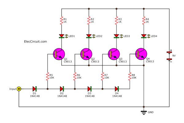
First, the input signal comes through D1, D2, D3, and D4, which serves two functions: rectifying the audio signal from AC to DC and dividing up the signal so that it gradually decreases after each one.
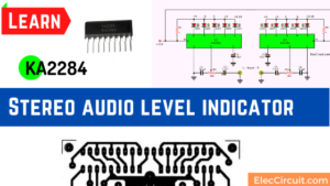
Related: KA2284 Stereo audio level indicator
The signal is then forwarded to Q1-Q4 through R5-R8. The resistors limit the bias current for the base of the transistors.
Transistors Q1-Q4 then drive LED1-LED4, where LED1 lights up when the audio signal is at its lowest and LED4 lights up when it is at its highest.
How does that work? Each diode has a voltage across it of 0.6V, and suppose the input signal has about 1.8V. This means that the current can only flow through the first three diodes, D1, D2, and D3; therefore, only LED1, LED2, and LED3 light up.
Buy an LED kit at Amazon.com here (affiliated link)
Improved 20 LEDs VU meter Circuit
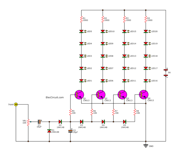
The main downside of the previous LED VU meter circuit was that it did not work at low voltages. To improve that, we are adding a voltage doubler circuit consisting of C1, C2, D1, and D2 to this circuit.
As the name suggests, they will increase the incoming AC voltage by approximately twofold. This higher voltage allows the transistors to drive more LEDs, bringing the total number of LEDs in this circuit to 20.
How it Works
After applying power to this LED VU meter circuit, the input signal passes through VR1, which allows us to adjust the input voltage as it arrives. Then, VR1 passes the signal to C1, acting as a signal coupler.
The signal then goes into D1 and D2, the part of the circuit that increases the voltage. Both diodes act as a rectifier, converting AC to DC and combining positive and negative results together.
After that, the increased voltage goes through the C1 filter capacitor and comes out as a smooth DC voltage.
Now the input signal comes to the VU meter part of the circuit. Overall, it functions similarly to the previous circuit. However, there are now five LEDs per row, as opposed to one.
When the audio signal is at its lowest, Q1 conducts current, and only LED1 through LED5 light up. As the audio signal strength rises, Q2, Q3, and Q4 gradually conduct current and light up their respective LEDs.
20 to 40 LEDs VU Meter Circuit
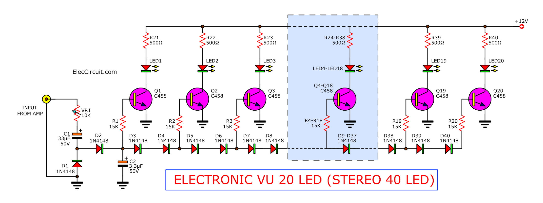
This LED VU meter circuit can directly drive 20 LEDs (40 LEDs for dual-channel stereo), which is not possible with a normal IC. Furthermore, this circuit can also be easily adapted to control a Solid State Relay to drive much larger lights.
How it Works
The input audio signal from an amplifier passes through VR1, which is used to adjust the amplitude of the input signal. The audio signal then goes through a voltage doubler rectifier circuit, consisting of C1, C2, D1, and D2.
After that, the audio signal comes to the main part of the circuit, where Q1-Q20 compares the amplitude of the signal. The voltage difference is set by D3-D40 at 2V increments.
Transistor Q1 works when the signal has the lowest voltage, whereas transistor Q20 works when the signal has the highest voltage. The voltage difference between each transistor is 2V.
In the circuit diagram above, the section of the circuit that has a dashed box around it indicates an identical repeat, and they consist of Q4-Q18.
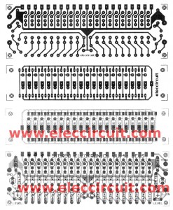
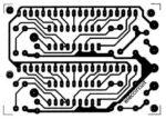
Building This Circuit
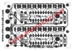
We assemble this circuit onto a PCB shown below. However, we need to be extra careful because this circuit has a lot of components with designated polarity, such as diodes, LEDs, and electrolytic capacitors.
There are things to do after finishing building this circuit. First, we apply the voltage power supply to the circuit. Then connect the audio signal from an amplifier to the input of this circuit.
Next, turn up the sound to the highest and adjust the VR1 until every LED lights up. That is it.
Components List
Q1-Q20: 2SC458, 2SC828,C945,C1815, 45V 0.1A, NPN Transistor
D1-D40: 1N4148, 75V 0.15A Diodes
R1-R20: 15K, Resistors 0.25W +/- 5%
VR1: 10K, potentiometer POT
C1: 33uF 50V, Electrolytic
C2: 3.3uF 50V, Electrolytic
L1-L20: LED 2 x 5 mm.
Note:
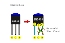
Those who cannot find C458 or C1815 transistors can substitute them with a 2N3904 transistor instead. However, the 2N3904 will have a different lead layout, so you will need to swap it around. You will need to be careful with short circuits or maybe add some insulators between B and C lead.
Note: This circuit worked well as Video below:
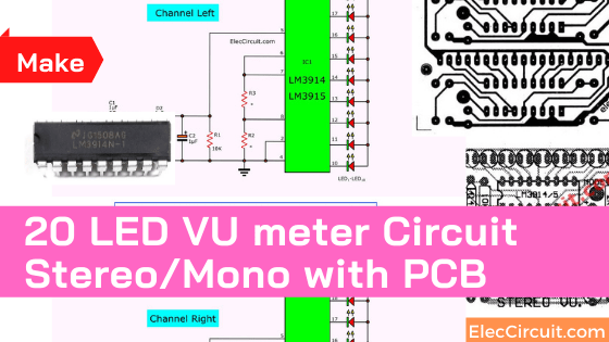
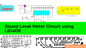
10/20 LED VU Meter Circuit for Mono/Stereo Using ICs
Here is an LED VU meter circuit using an LM3914 or LM3915 IC. For a single-channel mono audio signal, it can display 10 LEDs in total. However, for a dual-channel stereo audio signal, we can make two circuits and use one for each channel.
This circuit is quite popular; believe it or not, I have seen this VU meter circuit for about 40 years now, and there are still people using it today. It is also more convenient compared to a transistor-based circuit.
I have made a lot of amplifier circuits because I like listening to music. I also like VU meter circuits, as I think they visualize audio that we usually listen to very beautifully.
The reason for using the LM3914 or LM3915 is that they are very convenient and can be used for purposes other than the LED VU meter circuits. For example, using them to make a light decoration on a Christmas tree that changes according to the music.
But for this VU meter circuit in particular, it is very simple since it only requires the IC and a few other components. We can also configure the layout of the LEDs to be a BAR or a DOT design.
LM3914 vs. LM3915
This circuit can be built using either the LM3914 or LM3915. However, do note that these two chips have slightly different features. Here are the main differences between them.
- LM3914N will display the signal in a linear form.
- LM3915N will display the signal in a logarithm form.
- LM3916N allows for output to LCDs, vacuum fluorescents, and incandescent bulbs, as well as LEDs of any color.
Normally, if we want to accurately display the amplitude of an audio signal, we would choose the LM3915N.
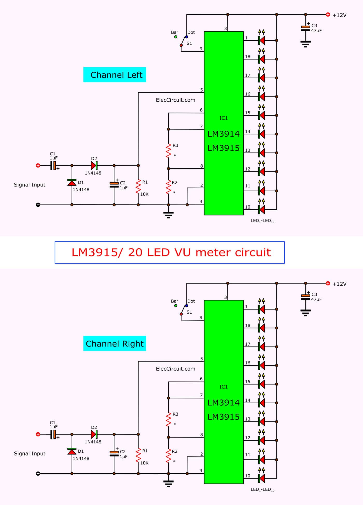
The Working Principle
In the circuit above, the input signal from the amplifier will enter through the voltage doubler circuit consisting of C1, C2, D1, and D2. They convert the AC audio signal to a DC signal with twice the amplitude of the input signal.
This signal then goes to pin 5 of the IC1, and the IC1 drives the LEDs according to the amplitude of the signal. The mode switch S1 is used to select between DOT and BAR mode. Disconnecting pin 9 resulted in BAR mode, whereas connecting it to the positive voltage of the circuit will switch to DOT mode.
As for the power supply, this LED VU circuit requires a 9V to 12V power supply, so here are a few options.
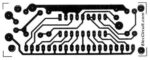
Building This Circuit
You can assemble the circuit on a perforated PCB since there are only a few components. Or you can use the PCB and components layout for both the stereo and mono versions below.
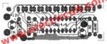
Caution: The LEDs must be placed in the correct polarity, or else the LEDs will not light up.
Components List
IC1: LM3914N, LM3915N, or LM3916 DOT/BAR display driver
D1, D2: 1N4148, 75V 150mA diodes
LED1-LED10, LED 2x5mm LEDs.
0.25W Resistors, tolerance: 5%
R1: 10K
R2: 2K
R3: 3.9K
Electrolytic Capacitors
C1, C2: 1uF 50V
C3: 47uF 16V
Note:
1. If you are printing the PCB above, use the 200 DPI per inch image scale.
2. The PCB layout above does not include the place for C3, so you might need to add it at the power supply terminal. Or if you are using a regulated power supply, you may not need it at all.

I love electronics. I have been learning about them through creating simple electronic circuits or small projects. And now I am also having my children do the same. Nevertheless, I hope you found the experiences we shared on this site useful and fulfilling.
I am finding a circuit to built my own timing light to adjust my engine timing, but i didn’t see such circuit in this. To everybody who knows how to built the timing light circuit, please send me one..
Hi man, if I use a microphone at Input will it work fine?
Pls can u develop a fm transmitter for cell phone(nokia c3.00) and send it to my email to download or do u has any suit for that pls let me know thanks.
Hi John Akam
I am not sure can help you made done project.
Please look at: https://www.eleccircuit.com/tag/house-fm-transmitter/
https://www.eleccircuit.com/fm-wireless-transmitter-circuit/ with PCB layout
Grazie per il vostro articolo esplicativo e per l’entusiasmante ora di elettronica che si prospetta per il prossimo futuro.
The English is perfect..Thank You for yet another GREAT PROJECT!!!!
Hi sir, good evening.
The project is simple and easy to do.
Thank you and tomorrow I’ll try to make it and use it for an electronic load control for coupling two inverters.
The firts is 48v DC to 220V pure sine wave stand alone about 300VA.
The second is grid connected to the first and works from 400v 1000W peak of solar panels .
When the sun is strong the energy breaks the first inverter and I need to put this energy gradually into a battery charger.
I’ll send you more comments.
Thank you
Gostei do circuito de vu vc podes mandar -me o layout do amplificador 22000wa
tts
I am sorry. I do not have 22000 watts amplifier circuit.
To jsou Paradni schemata ! Diky za ne ! To u nas tezko shanim,ale,tady najdu hodne paradnich schemat i plosne spoje ! Je to SUPER ! Dekuji ze mi to posilas ! Jirka – Czech Republic – Europe
Hello Podekovani!
Thanks for your visit. I am happy that you like this circuit.
Yes, You may use the universal PCB, too.
Thanks again,
Apichet
Muito bom o artigo..
Hello Zelino,
Thanks for your feedback. Happy New Year.
Have a great day.
Thanks
Apichet
You should connect a 1 kohm resistor in parallel to the 3.3 uf capacitor. Otherwise, the LED diodes turn off too late after a high signal.
Thank you for your valuable experience.
Hello, I come here from a video on Youtube, your projects are very interesting. You wrote that VU meters can be connected to speakers of a power amplifier. But how can they be adapted if the output power is very high, like 200-300 watts? Many tanks
Hello from Italy, very interesting projects. If I understand correctly these VU meters with transistors can be connected to the speaker output of power amplifiers. What is the maximum power they can withstand? Thank you
Hi,
Thanks for your feedback.
I’m sorry, my dad is not available at the moment. To answer your question, my father would like to explain it to you as much as possible. He likes to explain with pictures. 🙂
Hi, many thanks. It is very interesting to know the data on the maximum power because this VU meter is logarithmic and the LM3915 is very difficult to find as an original component and in any case it must be inserted between the preamplifier and the final amplifier.
First of all, thank you for your valuable question. This circuit is simple and cheap, but it has lower sensitivity than using LM3914 or LM3915 because those ICs are designed directly for VU-meter circuit, so they have higher efficiency.
In my opinion, if it responds to low sensitivity, you may add a pr-amplifier circuit before entering the input of this circuit.
However, I have not actually tested it, so it may be inaccurate, so I apologize in advance.
Thanks again.
Hello can you answer my question? Thank you, then I purchase your books
The fine back reduce through diode limits the moximum pewor sign respond. Same but more sensitised can be with resistor flailed.