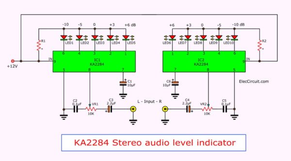
Here is a cheap Stereo audio VU meter circuit with PCB. This is the KA2284 audio level indicator. It is suitable for beginners or people who like to save.
Why?
This circuit is smaller and cheaper than other IC or even transistor circuits. In each channel is 5 LEDs.
After these 5 minutes, you will love it.

This LED meter can show the power of the output of the power amplifier. Also, It is a signal meter. It can measure the amplitude of the output signal in Tuner, CD player, and more. It is good quality very worth it.
How it works
First of all, the heart in the operation of the KA2284 audio level indicator. It is AC/DC 5-Dot Dual Led Level Meter Driver IC, in DIP-9.
Easy stereo VU-meter circuit using KA2284
Then, It is designed to display a bar. There is changing in Logarithm mode. It shows each of LEDs are -10, -5, 0, 3 and 6 dB.
Next, the output of this circuit can drive each LED that current higher up to 15mA
Last, the application of this project is very easy. Because it uses just two ICs and a few other components as above
Read: LED VU Meter Circuits using transistors
How to build this project
We can build this easy project. We just connect right all components as PCB layout. They will work for sure.
We have to be careful, LEDs, and electrolyte capacitors. Often we put them in the wrong polarity, which can damage them.
In addition Figure 2, shows PCB and device location. The beginner or safety should use the socket for IC. We may bring a normal 18 DIP socket, to cut into 2 the 9 pin socket. It is great I like it!

PCB Layout

Components Layout
Pin 1 is to Observe the index mark on one side of the IC. Sometimes it may round, there is the main point.
Keep reading: Peak Hold VU meter circuit »
When building completely then provides voltage to this circuit. Then, connect an output of a power amplifier to the input of this project.
Next, adjust the volume of the amplifier. We will see LED running beautifully as follows the amplitude of the input signal.
From the circuit to see that, we have to focus on the design the beautiful. LEDs run separated from each channel, from the center to the left and right. If you do not like its form, you can order it to a new LED model.
All components list
IC1, IC2: KA2284, AC/DC 5-Dot Dual Led Level Meter Driver
LED1-10: LED 5mm, as you like
R1,R2: 68 ohms, resistors 0.25W +/-5%
VR1,VR2: 10K, Potentiometer
C1,C6: 10uF 16V, Electrolytic capacitors
C2,C5: 0.1uF 50V, Polyester capacitors
C3,C4: 2.2uF 50, Electrolytic capacitors
…
Download This
All full-size images of this post are in this Ebook: Elec Circuit vol. 2 below. Please support me. 🙂
Note: Buy KA2284 Here
Keep reading:
- Analog VU meter schematics »
- Stereo/Mono 20 LED VU meter circuit with PCB »
- LM3914 Datasheet Dot/Bar Display Driver | VU Meter Circuits »
- 8 Low Battery Voltage Alarm indicator circuits »
GET UPDATE VIA EMAIL
I always try to make Electronics Learning Easy.
Related Posts

I love electronics. I have been learning about them through creating simple electronic circuits or small projects. And now I am also having my children do the same. Nevertheless, I hope you found the experiences we shared on this site useful and fulfilling.


Thank u all for helping me
WA DIHUBUNGI PENTING?
I am sorry. I cannot understand you said. Please type English.