There are many ways to build a light meter circuit. It is a tool to measure the quantity of light, widely used to a photography, To decide the correctness of the exposure.
Sometimes, we are use with other works, such as my son likes to use in science experiments, which do not need to have high quality.
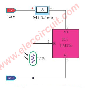
This simple light meter in figure 1 is an example circuit form LM134/LM234/LM334 datasheet of National Semiconductor (most popular IC), It takes very little equipment,
Features of the circuit, when there is a lot of light levels, an ammeter will show a high current, but a little light it will lower the current.
We use the light sensor device is the LDR( Light Dependent Resistors) which Normally the resistance of an LDR is very high, but when the light hits it, that has a lower resistance.
The LM334z is 3-Terminal Adjustable Current Sources, that the output of 1µA to 10mA with a resistor between pin 1 and 3, and used the power supply voltage input is a wide range of 1V to 40V.
The ammeter may be used the 0-1mA Analog DC Current Panel Meter Ammeter at amazon.com it low cost and FREE Super Saver Shipping.
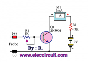
2. Using a general diode
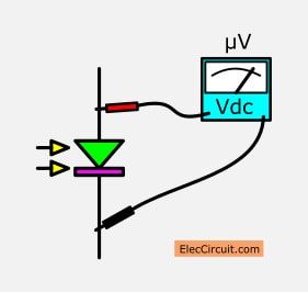
This is a simple light meter circuit using normal diode as a sensor and show amount of light by a any voltmeter.
The light can change the properties of many devices, example..
LDR as photo resistors can change resistance by light.
Photodiode- like LDR but sensitive better than LDR, because convert light into a electricity current.
Some times general photodiode may be expensive and hard to buy. When the light to a silicon diode will have very tiny current So we can easily use it instead.
Light meter Using a Diode
The 1N914 is popular number, cheapest, small and clear body. In reverse bias form, when light to it will cause a photo current leak through to a P-N junction.
How to choose the diode
+ We need the high sensitivity diode only.
+ Shine a flashlight or sunlight on the 1N914 diode.
+ In Figure 1, measure voltage by a digital voltmeter only, because the photo current is very very low, an analog meter cannot read.
+ If more light, will makes more diode current.
Current to voltage converter
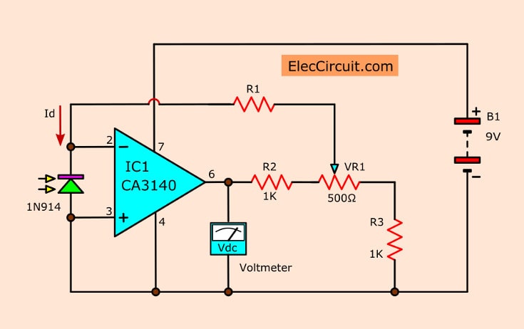
Then, apply it to a current to voltage converter circuit. In Figure 2. This circuit use the CA3140 OP-AMP on an inverting mode.
The resistor-R1 set a circuit’s gain, and the output voltage will rise if we increase R1’s resistance. Thus will get the formula is :
Vout = Id.R1
In this formula: Id = the diode current
The resistor R1 = 1M, but we may try to use 100 K to 10M, to adjust the proper gain ratio.
The voltage divider circuit include R2, R3 and VR1, to compare the circuit with the light meter calibration standard
How to setting
May use A 40-watt incandescent bulbs without Reflector. Placed away from the light meter is 50cm.(which will be a brightness of 150 lux approx.) Then adjust VR1 to read the Vout is the number 150 (1.5V). So, can use this to directly measure others brightness. If cannot read is 150, may be change the new R1’s resistor to lower or higher up.
We can use the analog voltmeter is cheap, or digital is easy to read and high correct than the analog types. Also, a vu-meter as galvanometer is cheapest but smallest.
The 1N914 diode have Parabolic reflector shape to increase the sensitivity and good direction. Be used aluminum foil as a reflective.
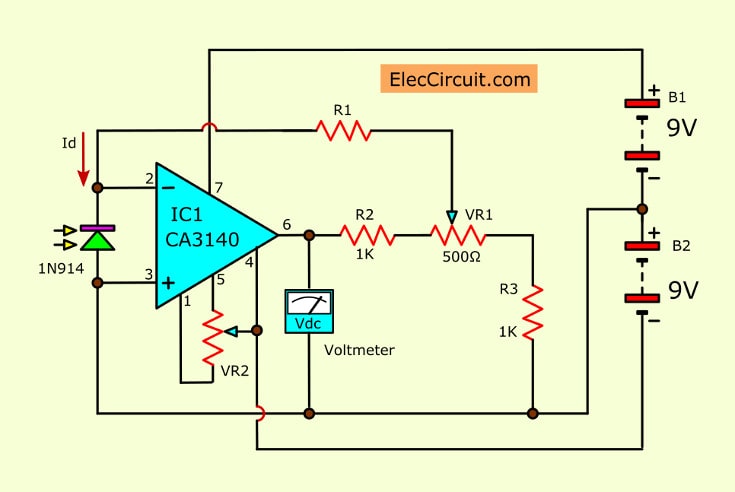
Figure 3 The full circuit diagram
In Figure 3. If need to measure a lower brightness, may add offset adjusting of op-amp and change the power supply is positive-negative types. If single power supply, can use voltage 6-30V, but dual types is 3-15V.
I love electronic circuit. I will collect a lot circuit electronic for teach my son and are useful for everyone.