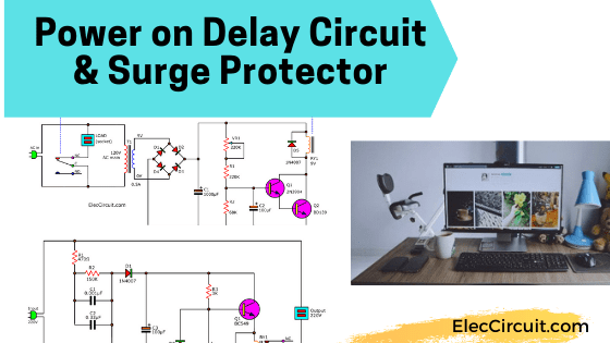
These are the power-on delay circuits or Surge protector circuits. They have the contact of relay acts as a switch. When we enter an AC main to these circuits. The circuits will delay the working for a load. Why should use it?

Imagine, it is raining and windy very heavily now. Until it occurs a power failure or voltage drop or flashing in a short period. Like this may cause the power surges severely.
Sure, it causes electrical appliances to be damaged. For example, Monitor, TV, refrigerator, computer, or others. Even this may result in lost data in a hard drive.
When a power surge occurs, what do you do? My mom often complains about having to unplug or turn off the TV immediately.
We can reduce this problem with a delay to turn on those appliances. Until the electrical system is normal. Which is inconvenient at all. We as electronic men…LOL. There should be an electronic solution to the problem.
Recommended: How does a SCR thyristor work?
We should have a system time delay. When a power failure occurs for a period of time. This system will not connect the AC line to the electrical appliances immediately.
But it will delay to turn on for a period of time. Then, the surging electrical away, the power system will continue to electrical appliances again.
Our electrical appliances are so safe. Without the worries. These surge protector circuits build simple and cheap.
I have 2 ideas to introduce you to.
Surge protector using delay system
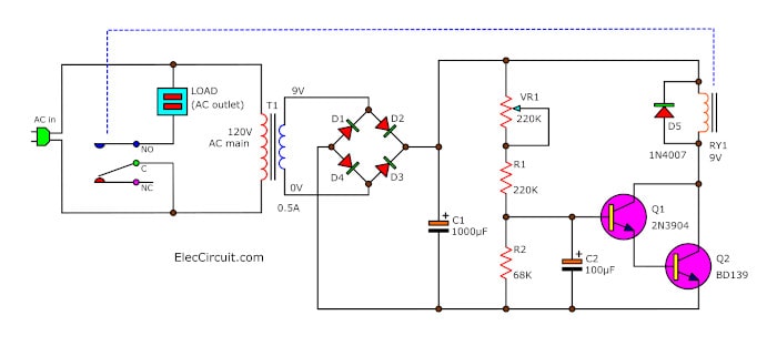
Look at the circuit diagram below. It uses the principle of a simple timing circuit, has Only a few more transistors and components.

How this circuit works
First, no AC power comes into this circuit. The relay’s contacts(RY1) NC and C are connected. So, making electrical appliances is not working.
Then, the AC power to the circuit, the primary coil of the transformer T1, the secondary coil. And, has an AC voltage is 9 volts.
Next, it is rectified from AC to DCV by diodes D1 to D4. And it is filtered to smooth DC voltage by C1.
Now, the voltage at C1 is about 12V(DC unregulated).
Next, the current flows to these parts, VR1, R1and R2. They help to divide the voltage to bias current to the base of transistor Q1. The Q1 does not work. Because the voltage of R2 is low.
The relays’ contacts (RY1) NC and C remain connected. The load does not runs. Until the delay system finishes the work.
How to delays
The C2 as acts the delay. It will store slowly charged, until enough to bias base current the Q1 works. Or
The VR1 is used to adjust the time delay. The electrical appliances do not run immediately. After the AC line flowing into this circuit.
When Q1 and Q2 transistors work. The contacts of the relay are switched to the NO (C connects NO contract).
Now, electrical appliances are ready to works.
In the event of a power failure the relay contact is connected to the NC. The RY1 will cut off electrical appliances out of the AC line.
For D5 will protect the transistor from the operation of the relay.
The parts of this circuit
- Q1: 2N3904, NPN small transistor.
- Q2: BD139, NPN medium transistor size
- R1: 220K 0.25W Resistor
- R2: 68K 0.25W Resistor
- VR1: 220K Trimpot
- D1-D5: Diode 1A 50V to 1A 1,000V; For example, 1N4001,1N4002 to 1N4007
- C1: 1000uF 25V, Electrolytic Capacitors
- C2: 100uF 25V, Electrolytic Capacitors
- RY1: Relay 9V coil, contact 3A 250V
- T1: 0.5A 9V Transformer
How to build
This project is easy to build. So you may assemble all components into a small perforated PCB.
I know that you can build them for beginners. But you should always set and be careful to check the circuit diagram before you insert the AC line onto this circuit.
I hope you enjoy this project.
Power on delay circuit without transformer
Caution! Before build this circuit below. Please think again carefully. It’s quite dangerous. Because it does not use a normal transformer. If touch this circuit get an ELECTRIC SHOCK.
Look at the circuit below. This is another idea. If you do not use a transformer in the power supply section. I am not telling you to build this circuit. We only use it for educational purposes.

The simple delay turn on the monitor circuit
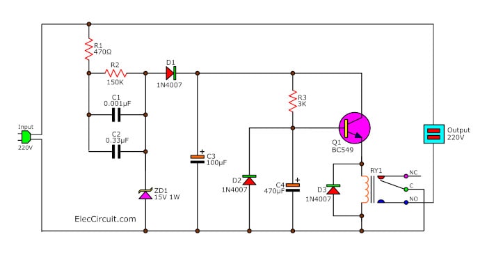
It looks like the previous circuit. It uses contact of the relay to act switches on-off to a load.
When 220-volts power inputs to the circuit. It is transformed to the lower voltage, 220 volts to 15 Volts. With these components R1, R2, C1, and C2. And the current limiting to about 41 milliamps.
There are the Zener diodes, ZD1 limited voltage to 15 volts. Then, the current flows through D1 to the rectifier as DC voltage. And C3 filters to a smoothing DC voltage.
In begin, the load does not run. because the contact of relay C-NC is connected.
While there will be current through R3 to charge C4. Which takes time to charge. When the C4 charge fully to make a current flowing into pin B of Q1.
The Q1 runs and drives currents to the coil of RY1. The switch contacts C-NO connects. It makes AC power comes to the load.
If you want a long delay. Add the capacitances of C4 more. On other hand, if you want to short delay, reduce the C4.
The Diode-D3 prevents reverse voltage from the coil of a relay. Which may be damaged to the circuit.
Note:
- Use low current of relay’s coil, like 12V 40mA.
- In my opinion, The designer should use a TRIAC instead of a relay because it consumes less power.
How to build this project
This project is not used many components, so can assemble on the universal PCB board. The wiring and various components to look out carefully for the polarity of the electrolytic capacitors, Diodes, Transistor, and relay are correct.
The components List
0.25W Resistors, tolerance: 5%
R1: 470Ω 1W
R2: 150K 0.5W
R3: 3.3K ¼W
Capacitors
C1: 0.01uF 250V, Polyester
C2: 0.33uF 250V, Polyester
C3, C4: 470uF 16V, Electrolytic
Semiconductors
D1-D3: 1N4007, 1000V 1A Diodes
ZD1: Zener diode 15V 1W
Q1: BC549 or 2N2222 Transistor
Others
RY1: Relay 12V see text
The universal PCB or Perforated PCB.
We recommended others delay circuits
- Simple time Delay Circuit using MOSFET
- 10 Second Fan on delay timer circuit by transistor
- Simple Switch off delay circuit using 2N4871
GET UPDATE VIA EMAIL
I always try to make Electronics Learning Easy.
Related Posts

I love electronics. I have been learning about them through creating simple electronic circuits or small projects. And now I am also having my children do the same. Nevertheless, I hope you found the experiences we shared on this site useful and fulfilling.


Why don’t you try learning English. I couldn’t understand a word of your jibberish.
Hello, John
Thank you for your suggestion. I am learning English, hope it will be more understanding.
Thanks again,