These are many ideas of the AC light dimmer circuit. Why use it?
Imagine in your bedroom too bright. Do you like it? Yes, you want to sleep well. Change a light bulb to low watts. It is not convenient. Some nights you want to read a book.
So, if you can adjust brightness. Is it great?
So what?
Let’s say you have an iron solder with a high wattage power, 60watts up. It cannot be used with newer ICs.

You can use the dimmer circuit to reduce wattage down, too.
What is more?
Reduce the heat of other electrical devices using coils.
It can adjust the fan motor speed as well.
Also, you can apply it to an automatic light dimmer
Sound good, is it?
Do not worry, these circuits do not hard for you.
They use the TRIAC and SCR as the main component and adjust potentiometer and switches.
See more projects circuits below:
- Low volts AC Dimmer for 6.3V Lamp
- Very Cheap AC light dimmer circuit
- Automatic Light Dimmer Circuit
- AC 100W Lights TRIAC Dimmer circuit
- AC light dimmer circuit using TRIAC and DIAC
- How to build AC light Dimmer
- Modify AC Dimmer to the automatic lighting
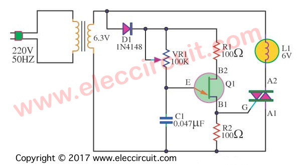
1# Low volts AC Dimmer for 6.3V Lamp
This is a low voltage AC dimmer circuit, for lamp 6V. While friends may not see the benefits of this circuit.
But I think that its an advantage in:
First step# We will learn the working of TRIAC.
Second, high safety, because of Low AC Voltage.
They have simple working.
The UJT-Q1, D1, VR1, C1, R1, R2 will generate frequency to actives the TRIAC. Then it makes the Lamp bright up.
Which the working rate of the TRIAC can be controlled by potentiometer-VR1.
So, It is a simple dimmer.
We may apply other level voltage of power supply, like AC12V.
The Q1 is UJT. For instance 2N4891 or others.
I hope this circuit will be ideas for friends.
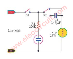
# 2: Very Cheap AC light dimmer circuit
Next, this is a very simplest AC light dimmer circuit, easy and inexpensive.
In the below circuit, we use the dimmer circuit with the AC power line.
So, we must be very careful.
How it works
Turn on S1 to ON and Select S2 to dimmer mode.
We use a capacitor in series with a lamp. The capacitor reduces power to the lamp.
S2 chooses an output power, full or less.
The value of capacitor-C1 depends on the size and power of the lamp, required brightness.
We may use several capacitors, to select the different capacity.
C1 should be a polyester capacitor or metalized polypropylene capacitors. And higher voltage than 400V.
Do not use the electrolyte capacitor in this circuit.
If the output short circuit, the C1 capacitor is damaged immediately.
This circuit is the easiest. But If you want easy adjusting.
How do we do it?
# 3: Automatic Light Dimmer Circuit
Imagine the light in the room gradually increasing as it begins to become the night. Is it good? Do not worry, it is easy with a few components.
Look at the circuit below.
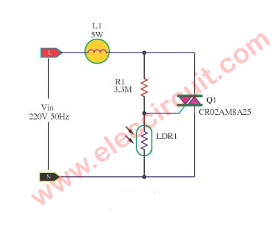
This is an automatic light dimmer circuit. You do not need to dim the lights by yourself. It is so very convenient because we use the LDR to detect external light. To control the Triac and the brightness of the lamp next.
How it works
Suppose that, Low light so there is the voltage across the LDR a lot. Makes a TRIAC works. And, the lamp is much bright
In contrast, it is daytime. LDR gets a lot of light, low resistance. The most current flows through it to grounds. So, There is low current to Triac. Then, the lamp does not work or low brightness.
In this circuit, we used only an incandescent light bulb, AC220V 50Hz at 5 watts. Because we can use low power Triac and basic circuits.
Important! Do not touch the circuit directly. You may be at risk of electric shock.
You just learn using Triac in basic. It works well, right?
We will use it in the dimmer circuit.
See below
Recommended: How does a SCR thyristor work?
# 4: AC 100W Lights TRIAC Dimmer circuit
This is a simple AC TRIAC dimmer circuit. We can dim the lamp up to 100 watts. If the TRIAC is a high temperature. It should be held with a large heat sink.
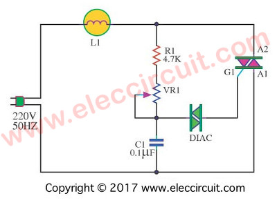
The DIAC(Diode AC bi-directional switch) is a kind of diode. It switches AC voltage or trigger to a gate of the TRIAC.
Adjust VR1 to dims the brightness of the lamp.
Caution! this circuit must be in an electricity insulation box that closes all the time. It has high voltage electricity flows through.
This circuit can work in under 100 watts load. But if you need more watts.
Look at the next circuit.
# 5: AC Light Dimmer Circuit Using TRIAC and DIAC
This circuit use more components than the above circuit. Sure, it is better.
How?
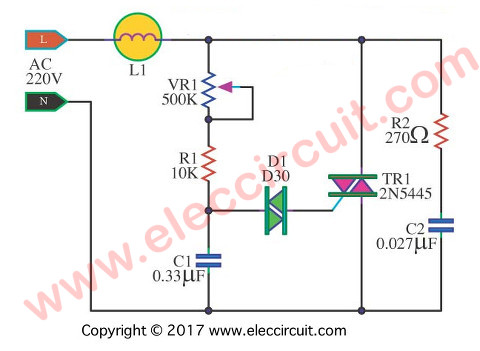
AC light dimmer circuit using TRIAC and DIAC (update from the Previous circuit)
Operation of the circuit
The lightness of lamp-L1 is adjusted by VR1. Which controls the speed of charging of C1. Then this charging voltage will control the works of Triac.
Suppose that we adjust VR1 less, C1 charges faster. It causes L1 is more brightest. In contrast, VR1 is much, C1 charges slowly. It makes L1 is less bright.
Because time periods that Triac runs are shorter than it does not run.
In conclusion, the brightness level of L1 will be adjusted according to the adjustment of VR1.
The R1 protects VR1 damage from too many currents.
R2 and C2 eliminate the disturbance signal, both inside and outside the circuit.
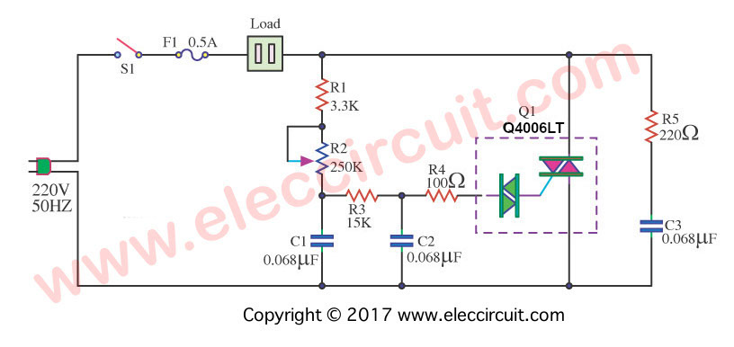
How to build TRIAC AC light Dimmer
You want to learn more. To try to create it yourself, right?
Look at the circuit. It is different above the circuit a little.
How it works
This circuit uses a special Triac with Diac inside it.
It is easy. And add some more a few components.
Sure, it is better.
How can we dim a light?
We know the AC main is the Sine waveform. Use Triac is an electronics switch. It works very fast in AC.
If we feed a different waveform in the gate of Triac. We can control it easily.
And Capacitors and resistors are basic components to change the waveform of AC.
Do you begin to understand?
Let me continue to explain to you.
Look at the circuit.
If VR1 is high resistance. The current flows to charge C1 slowly. And The gate of Triac will get a current slowly. But the AC main runs faster. So, at the load is sine wave not full. The light bulb goes out.
In contrast, we adust VR1 is low resistance. The current charges to C1 faster. Then, the gate of Triac gets the current fast, too. So, at the load is a quite full sine wave. The light bulb is bright up.
Double-time constant trigger
Why use C2, R3, and R4?
We called a double-time constant trigger circuit.
It helps us to adjust the brightness of the lamp or load smoothly. Not sudden like the above circuit.
How it builds
If you want to build this circuit, it’s very easy. You can assemble it on the Perforated PC board.
Or
Look at the PCB layout and component layout below.
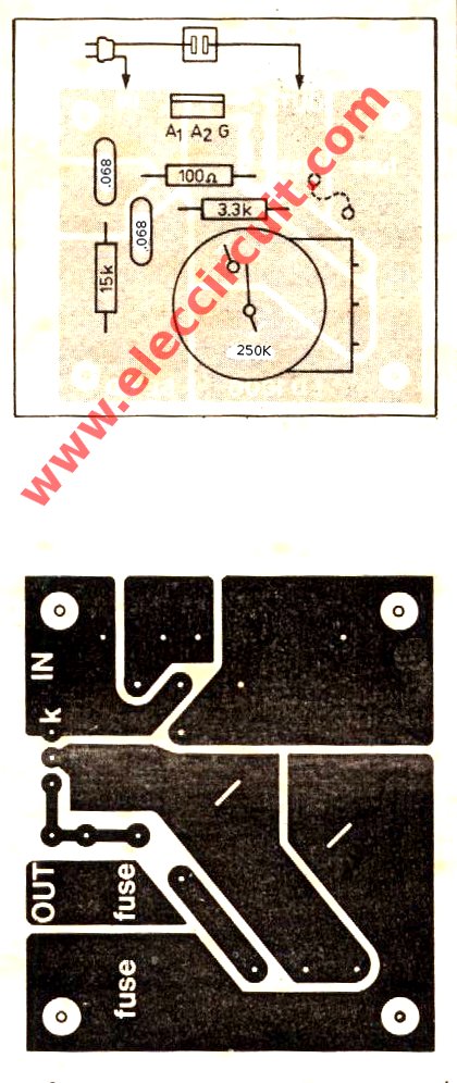
Figure 2: the PCB layout and Components layout of this circuit.
Note: Fuse you should as the current load. for example we use 100Watt lamp we will use fuse current is 100 watt / 220V = 0.45A or 0.5A.
Good suggestion
Mr. Gerson said about 1200 watts, AC Dimmer, using Triac Q4006LT
Why is 1200W dimmer when it uses 0.5A fuse? Is it should 5A fuse?
When you 0.5A fuse. It should be 120W dimmer by the maths.
Let’s calculate again:
Power (apparent since AC) = VI(rms) = 220Vac x 0.5A = 110VA (maximum, because of limiting of fuse)
Let’s assume a power factor of 1 (not possible in real using, unless 3 phase)
Power_in (max) = 110W.
Power_in (let’s said pf=0.7, realistic case) = 110 x 0.7 = 77W, this is more realistic power input.
So if power input is only about 77W. Please tell me. How it could output 1200W? It’s impossible according to the law of conservation of energy. The fuse will just BLOW every time it switches on at full brightness.
To get 1200W input for the typical realistic case.
You need:
Fuse rating (Irms)
= Pr / (V * pf)
= 1200 / (220 * 0.7) = 6.5A
Sure! You may not need the many currents. Since it is a dimmer. But at maximum brightness. You need to use 6.5A current. Otherwise, I am sure something will blow (the fuse).
Modify AC Dimmer to the automatic lighting
Way to modify an AC dimmer into a light switch circuit, to turn ON-OFF and automatic light dimmer or two in one form. Since the general dimmer uses TRIAC to control a load like a relay contact. So we can easily make it by a few parts.
The automatic night light dimmer circuit
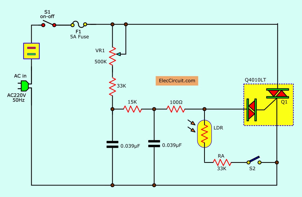
See Figure 1.
We put the parts includes S2, LDR, and RA-33K, 1/2W or RB to the AC dimmer circuit.
Turn-on a switch-S2, this circuit becomes the automatic light switch circuit.
When no light (or night) to LDR, the circuit will be closed, the lamp as the load will glow.
And a potentiometer VR-500K adjusts the sensitivity.
This can control an outdoor or car park lamps to ON with itself and OFF in day. LDR1 a kind NTC is when the light hits it, then its resistance will decrease.
The automatic Daylight dimmer circuit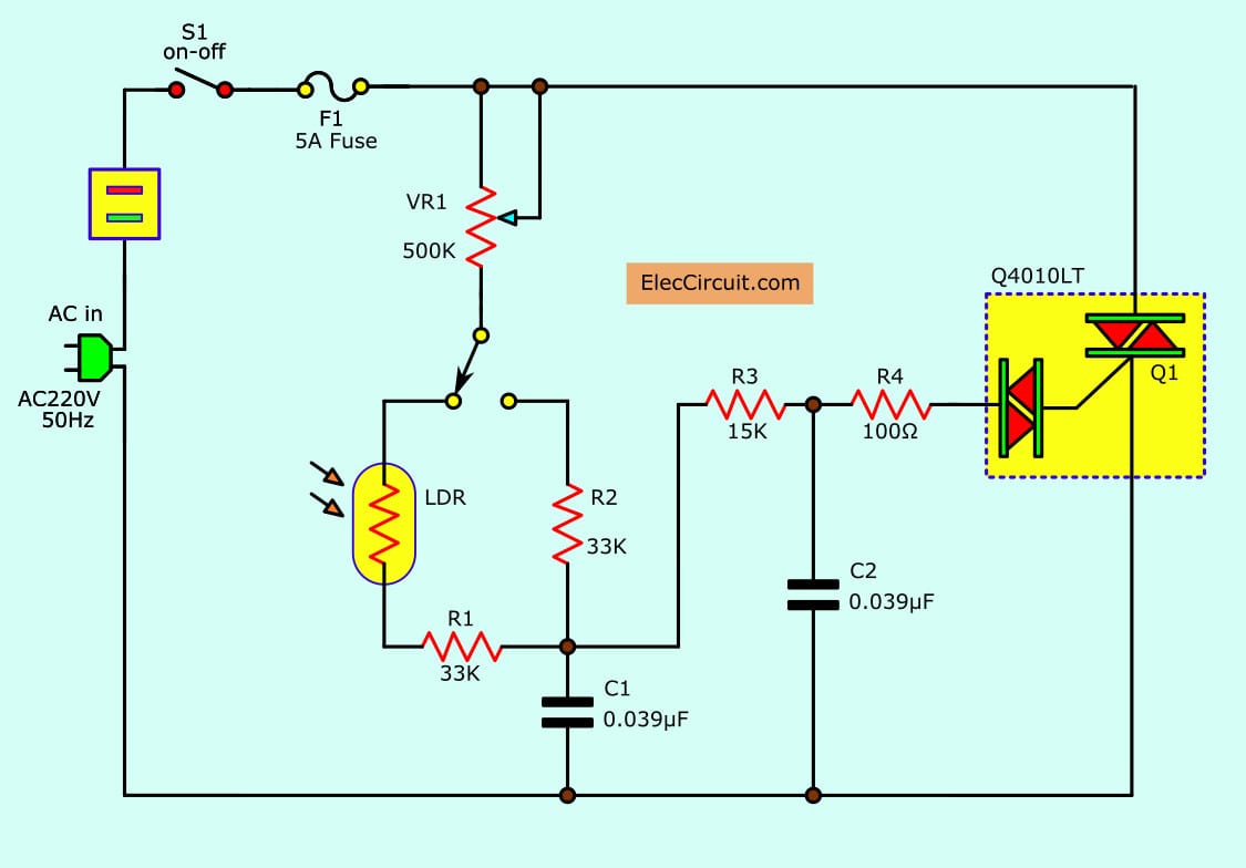
But in Figure 2 will work to reverse the first. Also, choose the switch-S2 to LDR1 way, then this circuit becomes the automatic daylight dimmer switch circuit.
This can control lamps in the Warehouse, if open the door and have sunlight to LDR, it will cause the lamp to glow.
LDR1 in Figure 2 is a PTC type. When the light strikes it. It will increase Resistance instead. This makes it possible to control the on-off. Or appropriate to the dimmer light outside.
LDR may be installed on the box or outside. But the important need far from the light enough. It will be a circuit does not operate correctly.
We can solder the more devices to the PCB and S1 may install in a box for safety when used.
3000 watts Dimmer for Inductor Load
GET UPDATE VIA EMAIL
I always try to make Electronics Learning Easy.
Related Posts


I love electronics. I have been learning about them through creating simple electronic circuits or small projects. And now I am also having my children do the same. Nevertheless, I hope you found the experiences we shared on this site useful and fulfilling.
Thanks for this simple circuit
what is the name of software this schematic is created by?
how can i design atriac circuit to control speed of motor 0.5kw?
can i havve the ckt for time period of 10 sec
hello
i dont full speaking english I want a circuit automatic ligh by senosr pir for turn off & turn off lamp (220AC) that day tur off & in night turn on whitout transformer for power sourc ic&…& whitout microcontoroler
what is the LDR used here? there is lot of confusion Here the LDR should act like a conductor at night and resistor in morning. so that the circuit works accordingly.
I’ll try to use R2, C2 to eliminate the noise. thx.
Can you be mo specific on what kind of diac to use in you figure 2 by L circuit?
I WANT 100 AMP DIMMER CIRCUIT DIA GRAM PLEASE HELP IN CIRCUIT
sir, i have 0.36uf/400v capacitor, what are the changes needed to the circuit
Dobry a uzitecny schemata ! Diky Ti priteli,ze mi je posilas ! 😉👍
Hi
Your article’s are good, thank you . I hope have useful days for electronic lovers.