VU meter circuit Stereo/Mono 20 LED with PCB
High-performance LM3914/LM3915 VU meter circuit projects that widely popular can display with 20 LEDs on stereo or mono with 10 LEDs for all audio systems. […] Read more
High-performance LM3914/LM3915 VU meter circuit projects that widely popular can display with 20 LEDs on stereo or mono with 10 LEDs for all audio systems. […] Read more
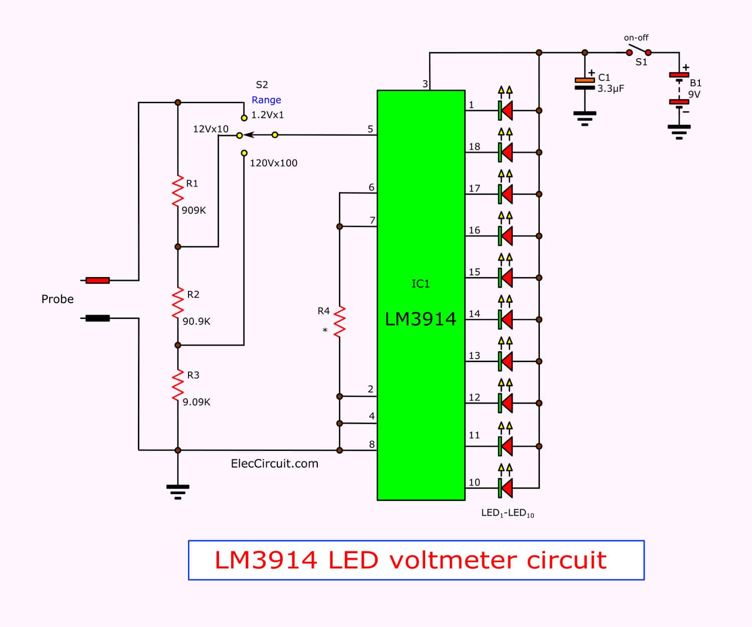
This is Simple LED voltmeter circuit using LM3914, can measure any volts 1.2V to 1200V on 3 range with 10 LED display easy to look and use 9V battery Read more
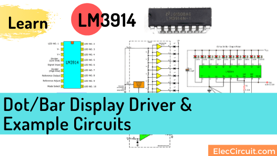
This LM3914 vu meter circuits, the VU meter kit, with the assembly various parts on their own or the style ready to use. Most of us are using the IC-LM3914 […] Read more