Soil moisture detector circuits and automatic controller
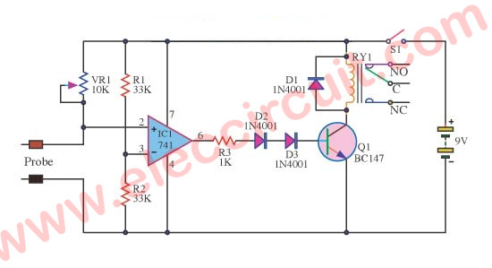
Simple ideals of soil moisture detector circuit projects, can alarm with LED and buzzer, and controller as water for plants Read more
Simple ideals of soil moisture detector circuit projects, can alarm with LED and buzzer, and controller as water for plants Read more