This is a megaphone circuit diagram using a signal sound amplifier from a condenser microphone to a higher signal at a small-sized loudspeaker.
There are two circuit diagrams to create. See below
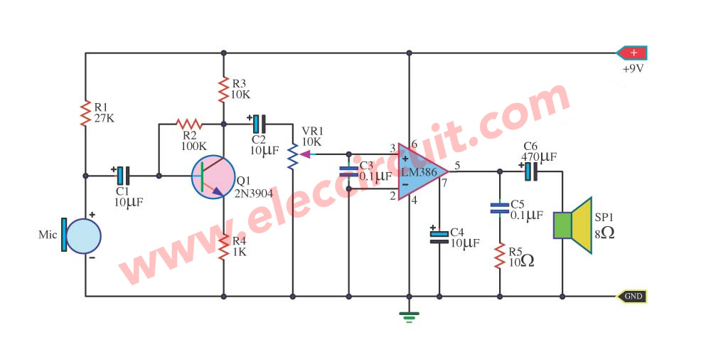
Simple LM386 megaphone circuit
It composes the importance is a microphone preamplifier (pre mic), use transistor just one enlarge sound signal gives the power goes up to mini amplifier with the IC(integrated circuit)LM386 audio amplifier chip to give a great sound at a loudspeaker.
How it works
When feed 9V power supply reach the circuit. The MIC1 and Q1 which be part pre mic, the mic will take the sound signal that has come in then deliver Q1 enlarge a signal has power size goes up to go out the way collector pin (C) change C2 coupling signal.
Then deliver with VR1 for fine signal sound level gives with Input of IC1. Which IC1 number LM386 be the integrated circuit amplifies 1-watt size has pin 3 are input and have C3 will eradicate source noise with input signal discharge down the ground.
When amplify finished will export comes to the way output pin 5 by have C5 and R5 eradicate a signal takes to stir go out sound signal will have that to change go to still.
The C6 coupling signal enhances the sound quality of low frequency improves. Before reaching, a loudspeaker makes a noise to come out.
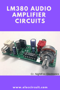
LM380 Simple megaphone circuit
Here is another Simple Megaphone circuit. lightweight portable size, 5-watt sound. It is suitable for your uses at any time. You do not need to speak loudly. It will boost up your voice to higher.
In the circuit using LM380 is a power amplifier and output to a mini speaker. It uses a 9V battery as a power supply. Because we want small size and cheap. You can do it!
How the circuit works
When we press the switch-S1. The circuit is working. But no sound came out.
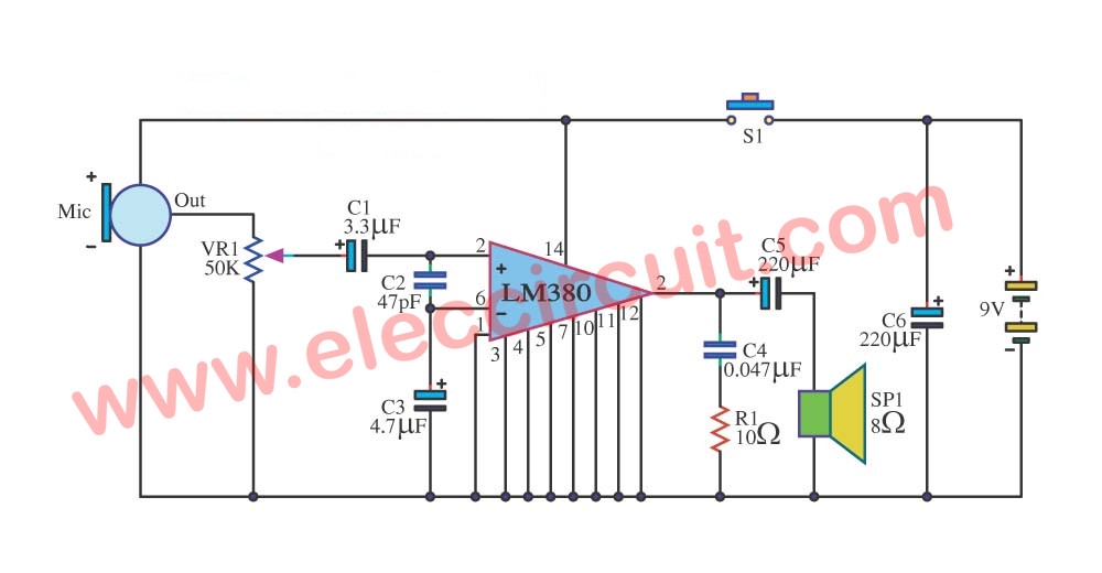
Then, when any sounds to MIC1, a condenser microphone. It converts these sound signals to electrical signals.
Next, it comes to the potentiometer-VR1(Volume) to adjust this signal before to C1.
C1 is a coupling capacitor. It allows or filter the only audio signal through it, and block DC from the input.
The audio signal comes to IC1-LM380—Mini Power Amplifier IC—. When we use it the life is easy. It requests a few components only.
Short Features
- Wide Supply Voltage Range: 8V-22V
- Voltage Gain Fixedoutput0
- Max watts ouput: 5W
- Low Quiescent Power Drain: 0.13W (At voltage supply is 18V)
- High Peak Current Capability: 1.3A
The higher audio signal rises out of Pin 8 to the output coupling-C5. And finally, to drive the speakers.
In addition, the R1 and R4 protect all noise signals.
Components List
IC1: LM380 mini power amplifier
Electrolytic capacitor
C1: 3.3uF 25V
C3: 4.7uF 25V
C5,C6: 220uF 25V
Ceramic capacitors
C2: 47pF 50V
C4: 0.047uF 50V
R1: 10 ohms 0.25W resistor tolerance: 5%
VR1: 50K Potentiometer
Related Posts

I love electronics. I have been learning about them through creating simple electronic circuits or small projects. And now I am also having my children do the same. Nevertheless, I hope you found the experiences we shared on this site useful and fulfilling.
does thos ckt work.?
My circuit doesn’t work.can you give me trouble shooting tips?
hey bro its working good thank you for this circuit. guys u have any problem u can mail me to this ID ([email protected])
cancel my previous comment, please.I had mistakenly read 386 in place of 380.
Hello Michael Bloom,
Thanks for your question. If you finish this circuit please share with me.