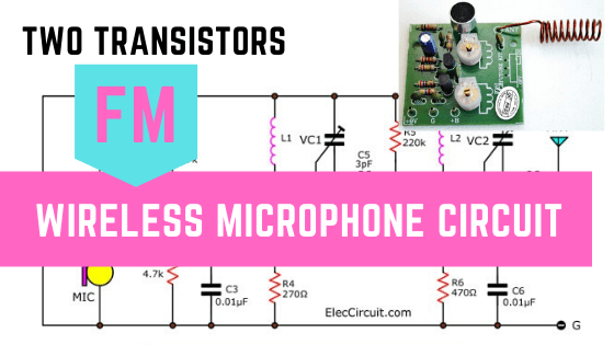
I have ever shown you an FM Wireless Microphone circuit. It is good to play with our kids. Or Learn RF transmitter circuit works.
But, is the distance too short?
Try this circuit. Add another one transistor in an RF amplifier.
So, this has two resonance circuits, and also two trimmers. Cause Higher efficiency and more transmission far up.
Technical information.
- Use DC Power supply of 9V
- Maximum consumption current about 10mA
- Transmission frequencies in the 88 MHz.
- PCB dimensions: 1.64 x 1.54 inches.
How does FM wireless microphone works
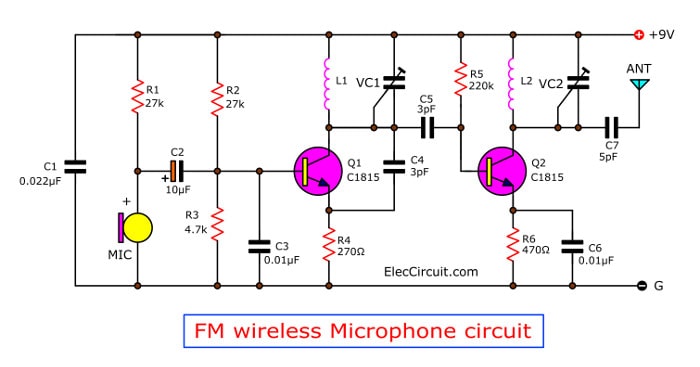
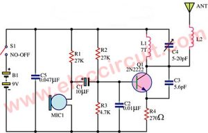
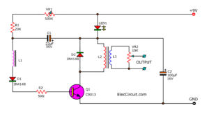
Figure 1 Two transistors FM wireless microphone circuit
Look at Figure 1:
A MIC1-condenser microphone is an audio receiver. It converts our voice to an audio signal.
Then, the signal flows C2 is a coupling capacitor into the base of Q1-transistor.
Which this transistor and a few parts around itself, have 2 functions.
First, generate high-frequency oscillators.
Second, mix audio signal into radio frequency (RF).
Then, the RF signal comes to the base of Q2 through the coupling capacitor-C5. The Q2 amplifies the RF goes out of a collector.
Then, send out to an antenna.
At collector lead of Q1 and Q2 have copper wires. They are working as a general coil.
How to builds its.
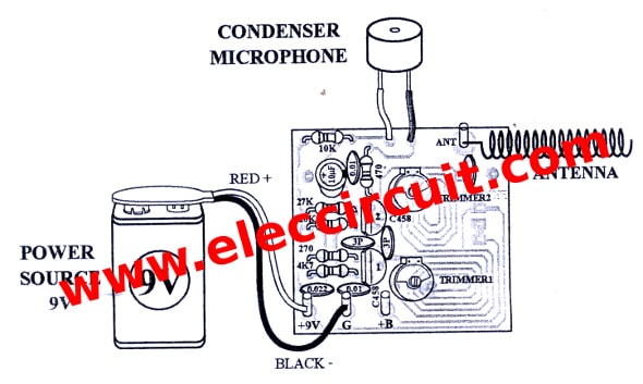
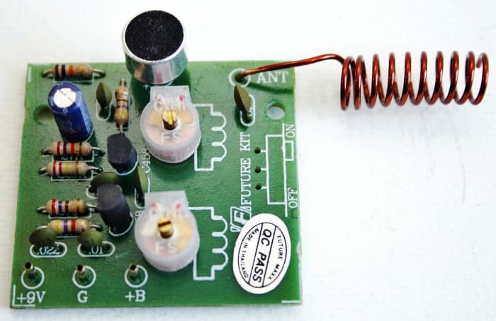
As Figure 2, the components layout and wiring of this project.
I am so sorry for cannot show PCB layout for you.
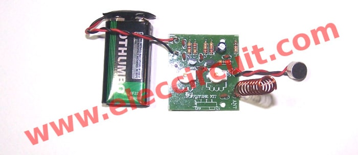
Then Figure 3, the complete FM wireless microphone circuit on PCB.
Testing the FM wireless microphone
First, apply the 9 volts battery to the positive terminal (+9V) and negative (G terminal).
Second, for ANT point connects to the coil.
You have to scrape off the enamel of copper coil. before soldering it.
Then, Set the FM radio stations to positions 88 MHz.
Next, use a plastic screwdriver to gently adjust the trimmer VC1, Until it whistles howling out the radio.
After that, try to speak into the microphone.
However, if no sound on speakers. You may try to turn the radio to about 100MHz.
If this is still no sound, you turn the radio all the way to 108MHz and try again.
Then, adjust Trimmer-VC2 in order to get more distance.
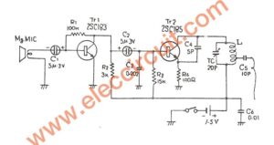
Also FM wireless transmitter
The components list
R1, R2: 27K
R3: 4.7K
R4: 270 ohms
R5: 220K
R6: 470 ohms
ELECTROLYTIC CAPACITOR
C2: 10uF
CERAMIC CAPACITORS
C1: 0.022uF (223)
C3, C6: 0.01uF(103)
C4, C5: 3pF
C7: 5pF
TRANSISTORS
Q1, Q2: 2SC458, 2SC828, 2SC945, 2SC1815
B1: 9-volt battery Or 9V power supply circuit
I am happy to see to save time. I found this project on Amazon

Related Posts

I love electronics. I have been learning about them through creating simple electronic circuits or small projects. And now I am also having my children do the same. Nevertheless, I hope you found the experiences we shared on this site useful and fulfilling.
how can i get the pcb for this project?
because the coils is printed on board
Hi,ami rosenberg
Thanks for your feedback.
I am sorry for not have PCB layout.
what distance it work?
please tell me
Hi may I know the value of the trimmer and the L1
Hi,All
I am sorry this is circuit Kit only.
so I can not show you trimmer and L1
hi there!nice project.i wonder if this could be used for guitar to have a simple wieless guitar system?will i be modifying the circuit if this would be used as such?thanks in advance
hi I cannot know the value of the trimmer.