Have you ever built a LED running light circuit? Many people like these circuits, me too. I am going to show you how to use the LED chaser circuit using Arduino.
We can easily apply or change coding. And once you know the working principle. Creating a 12 LED chaser circuit is also not difficult. and we can control its speed through the potentiometer too
3 LED running light using Arduino
This is the easy 3 LED running circuit or LED Chaser using Arduino. We will learn code “int” to define the variable.
-variable Is representatives of the various
Let’s write code Sample one LED flasher. Which we’ve already made easiest it
——code Sample one LED flasher use int on Arduino
int pin1 = 13;   // to define the variable

void setup()
{
 pinMode (pin1, OUTPUT);  // pin1 = 13
}
void loop()
{
digitalWrite(pin1, HIGH);
delay(1000);
digitalWrite(pin1, LOW);
delay (1000);
}
++++++++++++
How it works
From the code above. We use “int” to define the variable: pin1 = 13
The number 13 is the output of Arduino use for LED
In void setup() we set pinMode(pin1, OUTPUT) Which pin1 is 13.
Summarize: To see that we can use the command “int” To determine the variables To represent the various Easier to understand.
Let’s builds the 3 LED Running
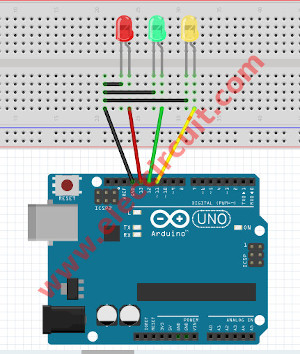
Next, we try to make the 3 LED Running using Arduino as Figure 1
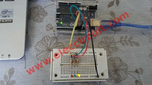
and Figure 2 is circuit connection
Then, next, let’s write the code 3 LED Running without int on Arduino
–—code—-
  void setup() {
  pinMode(13, OUTPUT);
  pinMode(12, OUTPUT);
  pinMode(11, OUTPUT);

}

void loop() {
  digitalWrite(13, HIGH);
  digitalWrite(12, LOW);
  digitalWrite(11, LOW);
  delay(1000);
  digitalWrite(13, LOW);
  digitalWrite(12, HIGH);
  digitalWrite(11, LOW);
  delay(1000);
  digitalWrite(13, LOW);
  digitalWrite(12, LOW);
  digitalWrite(11, HIGH);
  delay(1000);
}
We will see that, although the shortcode. If you want to change pin output 13,12,11 into others pins (for example 10,9,8). It must change several points so inconvenient. Or code: delay (1000) To change the time delay is 100 (0.1S) or p2000 (2S) will be edited together three positions. If our code long, it is very difficult to edit.
The 3 LED Running with int on Arduino
From these problems, let’s use an int as well.
int red = 13; => for the red LED pin have variable is “red”.
int green = 12; => for the green LED pin have variable is “green”
int yellow = 11; => for the yellow LED pin have variable is “yellow”
int delay1 = 1000; => for times value have variable is “delay1”
—-code—-
int red = 13;
int green = 12;
int yellow = 11;
int delay1 = 1000;

void setup() {
  pinMode(red, OUTPUT);
  pinMode(green, OUTPUT);
  pinMode(yellow, OUTPUT);

}

void loop() {
  digitalWrite(red, HIGH);
  digitalWrite(green, LOW);
  digitalWrite(yellow, LOW);
  delay(delay1);
  digitalWrite(red, LOW);
  digitalWrite(green, HIGH);
  digitalWrite(yellow, LOW);
  delay(delay1);
  digitalWrite(red, LOW);
  digitalWrite(green, LOW);
  digitalWrite(yellow, HIGH);
  delay(delay1);
}
We try to test this code is OK! Done complier and Good upload.
As Video below.
What is more? We will learn more LED displays. See below!
5 LED Chaser using Arduino
Today we will make a 5 LED chaser using Arduino. It can adjust speed by the potentiometer. Which LED Chaser circuit like this We’ve created a long time ago. But today we try to use Arduino. We are writing technical code “LOOP FOR” very interesting.
Recommended:
Parts you will needs
First of all, we need to have parts below:
- Arduino UNO R3
- Potentiometer 100K
- Five LEDs
- Five 470 ohms resistors
- Jumper wires
- Breadboard
Secondly, see the schematic diagram as Figure 1
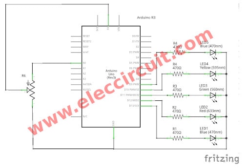
Figure 1 Schematic diagram of LED Running circuit using Arduino
Then, assemble parts on a breadboard and cable to USB port.
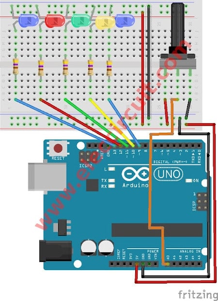
Figure 2 Circuit connection
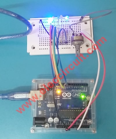
Figure 3 5LED Chaser-Potentiometer using Arduino
We use LED1-LED5 output display at D9-D13 pins. And A0 pin is used to read analog voltage from potentiometer.
Code programming
int LED1 = 9;
int LED2 = 10;
int LED3 = 11;
int LED4 = 12;
int LED5 = 13;
int delay1;
void setup() {
  pinMode(LED1, OUTPUT);
  pinMode(LED2, OUTPUT);
  pinMode(LED3, OUTPUT);
  pinMode(LED4, OUTPUT);
  pinMode(LED5, OUTPUT);
  pinMode(A0, INPUT);
  pinMode(9, OUTPUT);
}

void loop() {

  delay1 = analogRead(A0);
  //  analogWrite(9, val / 4);
  digitalWrite(LED1, HIGH);
  digitalWrite(LED2, LOW);
  digitalWrite(LED3, LOW);
  digitalWrite(LED4, LOW);
  digitalWrite(LED5, LOW);
  delay(delay1);
  digitalWrite(LED1, LOW);
  digitalWrite(LED2, HIGH);
  digitalWrite(LED3, LOW);
  digitalWrite(LED4, LOW);
  digitalWrite(LED5, LOW);
  delay(delay1);
  digitalWrite(LED1, LOW);
  digitalWrite(LED2, LOW);
  digitalWrite(LED3, HIGH);
  digitalWrite(LED4, LOW);
  digitalWrite(LED5, LOW);
  delay(delay1);
  digitalWrite(LED1, LOW);
  digitalWrite(LED2, LOW);
  digitalWrite(LED3, LOW);
  digitalWrite(LED4, HIGH);
  digitalWrite(LED5, LOW);
  delay(delay1);
  digitalWrite(LED1, LOW);
  digitalWrite(LED2, LOW);
  digitalWrite(LED3, LOW);
  digitalWrite(LED4, LOW);
  digitalWrite(LED5, HIGH);
  delay(delay1);
}
Code programming
We use this circuit to set 5 LEDs section. each section we define a LED LOW-HIGH as schedule.
1. Set int LED1-LED5 as pin output 9-13
2. Set “pinMode(9-13)” as output
3. Use “pinMode A0 as INPUT that read a voltage from potentiometer.
But we see that it have too many code.
LOOP FOR
We use loop FOR for shorter code. Below!
int delay1;  // to define the variable
void setup()
{
  for (int i = 9; i <= 13; i++)
  {
    pinMode(i, OUTPUT);  //to define the variable as output
  }
}

void loop()
{
  delay1 = analogRead(A0); //to read voltage at (A0) pin

  {
    for (int i = 9; i <= 13; i++)
    {
      digitalWrite(i, HIGH);  //to set “i” to “High”
      delay(delay1);   //to delay code as “delay1” or control speed by potentiometer
      digitalWrite(i, LOW); //to set “i” to “High”
    }
  }
}
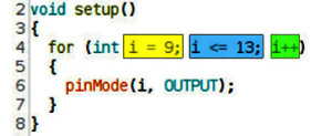
Figure 4 Code use loop FOR function
YELLOW: The variable “i” start is “9”
BULE: Define variable “i” max to “13”
GREEN : Define step up variable “i”
It makes variable “i” is incremented by step. (9 to 13)
We will see that our code short and easy.
We test to rotate the potentiometer to adjust speed of LEDs. As Video below.
We edit delay time easily! If you do not understand the programming.
Please read back.
How to use Arduino UNO | Programming C | LED Flasher | Potentiometer
GET UPDATE VIA EMAIL
I always try to make Electronics Learning Easy.

I love electronics. I have been learning about them through creating simple electronic circuits or small projects. And now I am also having my children do the same. Nevertheless, I hope you found the experiences we shared on this site useful and fulfilling.

hello
its very nice i want know how i do with pic 12f675 smae function using variable resister and 3 led can you help me please
Hello Yogesh,
Thanks for your visit. How are you?
Oh…it is so good. The PIC12F675 is a small Microcontroller DIP8 chip. I have never used it. I am so sorry that can not help you now. But I will learn to use it surely. In the next, we will share it. I believe you will use it well.