This is a simple audio peak limiter circuit. Why should you build it? In the standard audio generators. Its output level must not exceed 1Vrms.
But now, an audio signal generator may produce a signal to an over a limited standard level.
But the sound signal changes waveform. For example, we feed the input a sinewave.
It may make a bad result to an input of the stereo power amplifier. Which a normal power amplifier needs a signal input under 1Vrms.
If it is a higher signal. It still amplifies audio up to a higher level.
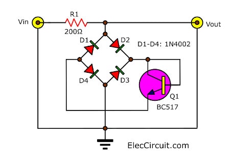
Simple audio peak limiter circuit diagram
But now the output may be a square wave.
We need just the sine wave that is a higher volume on a loudspeaker.
It may make oscillated, too. Which the power amplifier and loudspeaker are damaged.
Thus, this circuit will protect the input of power amplifier away high amplitude, more than 1Vrms.
Let’s learn more.
How it works
If you see the circuit, it may make you smile. It uses 5 components only.
Do not wait!
Build it! We install it between the signal generator and the power amplifier.
When there is an input voltage flows through R1 to limit currents down.
Then, the current comes D1-D4, in bridge diodes form. They are full-wave rectifier circuit to convert ACV to be DCV. Why?
Because the Q1 is an NPN transistor, it likes DCV. But it will start working when the input voltage is more than 1V RMS.
The transistor-Q1 will conduct the current. Between the collector and emitter looks like the short circuit.
So, the input signal cannot come to the out to the input of the power amplifier.
Parts you will need
0.5W Resistors, tolerance: 5%
R1, 200 ohms
Semiconductors:
Q1: BC517, 45V 100mA NPN Transistor
D1-D4: 1N4002 or 4148, 75V 150mA Diodes
Here are a couple of related articles you should read, too:

Related Posts
I love electronic circuit. I will collect a lot circuit electronic for teach my son and are useful for everyone.